HP ProLiant DL288 HP ProLiant DL288 G6 Server Maintenance and Service Guide - Page 78
To apply the thermal grease compound, CAUTION, To install a processor, DO NOT REMOVE
 |
View all HP ProLiant DL288 manuals
Add to My Manuals
Save this manual to your list of manuals |
Page 78 highlights
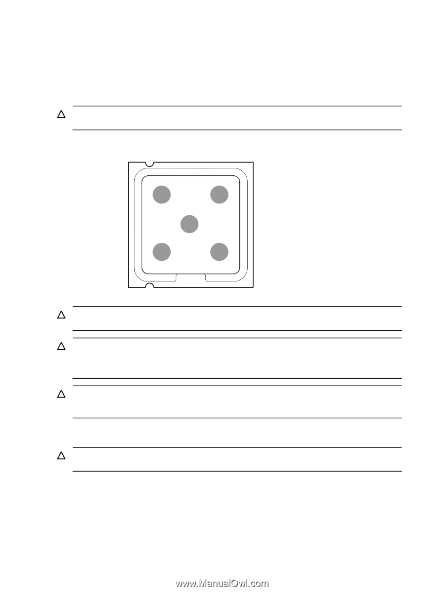
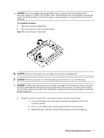
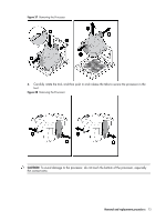
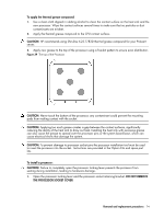
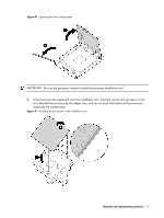
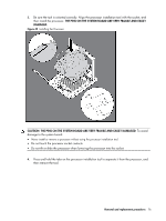
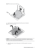
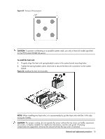
To apply the thermal grease compound: 1. Use a clean cloth dipped in rubbing alcohol to clean the contact surface on the heat sink and the new processor. Wipe the contact surfaces several times to make sure that no particles or dust contaminants are evident. 2. Apply the thermal grease compound to the CPU contact surface. CAUTION: HP recommends using Shin-Etsu X-23-7783D thermal grease compound for your ProLiant server. 3. Apply new grease to the top of the processor using a five-dot pattern to ensure even distribution. Figure 39 The top of the Processor CAUTION: Never touch the bottom of the processor; any contaminant could prevent the mounting pads from making contact with the socket. CAUTION: Applying too much grease creates a gap between the contact surfaces, significantly reducing the ability of the heat sink to draw out heat. Installing the heat sink with excessive grease can also cause the grease to spread over the processor pins or the system board base, which can cause electrical shorts that damage the system. CAUTION: To prevent damage to processor socket pins the processor installation tool must be used to insert the processor into the socket. Instructions are provided in the Option Kits and spare part kits. To install a processor: CAUTION: Failure to completely open the processor locking lever prevents the processor from seating during installation, leading to hardware damage. 1. Open the processor locking lever and the processor socket retaining bracket. DO NOT REMOVE THE PROCESSOR SOCKET COVER Removal and replacement procedures 74
-
 1
1 -
2
-
3
-
4
-
5
-
6
-
7
-
8
-
9
-
10
-
11
-
12
-
13
-
14
-
15
-
16
-
17
-
18
-
19
-
20
-
21
-
22
-
23
-
24
-
25
-
26
-
27
-
28
-
29
-
30
-
31
-
32
-
33
-
34
-
35
-
36
-
37
-
38
-
39
-
40
-
41
-
42
-
43
-
44
-
45
-
46
-
47
-
48
-
49
-
50
-
51
-
52
-
53
-
54
-
55
-
56
-
57
-
58
-
59
-
60
-
61
-
62
-
63
-
64
-
65
-
66
-
67
-
68
-
69
-
70
-
71
-
72
-
 73
73 -
 74
74 -
 75
75 -
 76
76 -
 77
77 -
 78
78 -
 79
79 -
 80
80 -
 81
81 -
 82
82 -
 83
83 -
84
-
85
-
86
-
87
-
88
-
89
-
90
-
91
-
92
-
93
-
94
-
95
-
96
-
97
-
98
-
99
-
100
-
101
-
102
-
103
-
104
-
105
-
106
-
107
-
108
-
109
-
110
-
111
-
112
-
113
-
114
-
115
-
116
-
117
-
118
-
119
-
120
-
121
-
122
-
123
-
124
-
125
-
126
-
127
-
128
-
129
-
130
-
131
-
132
-
133
-
134
-
135
-
136
-
137
-
138
-
139
-
140
-
141
-
142
-
143
-
144
-
145
-
146
-
147
-
148
-
149
-
150
-
151
-
152
-
153
-
154
-
155
-
156
-
157
-
158
-
159
-
160
-
161
-
162
-
163
 |
 |