HP ProLiant DL288 HP ProLiant DL288 G6 Server Maintenance and Service Guide - Page 48
Drives, Cable management
 |
View all HP ProLiant DL288 manuals
Add to My Manuals
Save this manual to your list of manuals |
Page 48 highlights
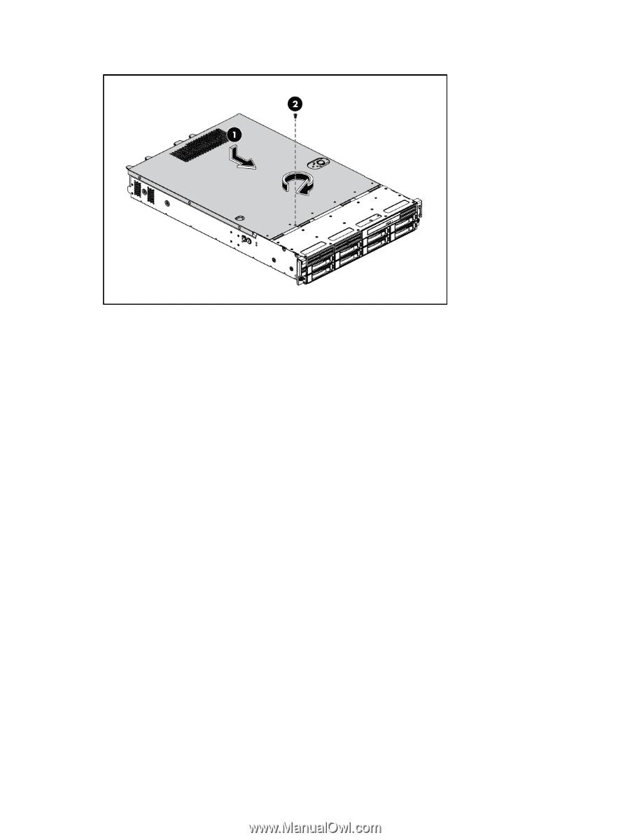
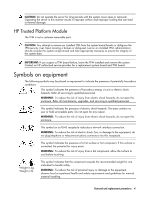
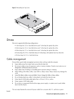
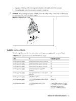
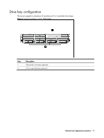
Figure 2 Reinstalling the Top Cover Drives The server supports the following configurations: • 4 drive bays for 3.5 in. hard disk drives and 1 drive bay for optical disc drive • 8 drive bays for 3.5 in. hard disk drives and 1 drive bay for optical disc drive • 8 drive bays for 2.5 in. hard disk drives and 1 drive bay for optical disc drive •12 drive bays for 3.5 in. hard disk drives (14 drive bays with optional rear two drive kit) • 25 drive bays for 2.5 in. hard disk drives Cable management Always follow good cable management practices when working inside the computer. • Keep cables away from major heat sources like the heat sink. • Do not jam cables on top of expansion cards or memory modules. Printed circuit cards are not designed to withstand excessive pressure. • Keep cables clear of sliding or moveable parts to prevent cutting or crimping. • When folding a flat ribbon cable, never fold to a sharp crease. Sharp creases may damage the wires. • Some flat ribbon cables come pre-folded. Never change the folds on these cables. • Do not sharply bend any cable. A sharp bend can break the internal wires. • Never bend a SATA data cable tighter than a 30 mm (1.18 in.) radius. • Never crease a SATA data cable. • Do not rely on components like the drive cage, power supply, or system cover to push cables down into the chassis. The next steps illustrate the removal of power cable from connector J60, 51, and 64 on system board. Removal and replacement procedures 44
-
 1
1 -
2
-
3
-
4
-
5
-
6
-
7
-
8
-
9
-
10
-
11
-
12
-
13
-
14
-
15
-
16
-
17
-
18
-
19
-
20
-
21
-
22
-
23
-
24
-
25
-
26
-
27
-
28
-
29
-
30
-
31
-
32
-
33
-
34
-
35
-
36
-
37
-
38
-
39
-
40
-
41
-
42
-
 43
43 -
 44
44 -
 45
45 -
 46
46 -
 47
47 -
 48
48 -
 49
49 -
 50
50 -
 51
51 -
 52
52 -
 53
53 -
54
-
55
-
56
-
57
-
58
-
59
-
60
-
61
-
62
-
63
-
64
-
65
-
66
-
67
-
68
-
69
-
70
-
71
-
72
-
73
-
74
-
75
-
76
-
77
-
78
-
79
-
80
-
81
-
82
-
83
-
84
-
85
-
86
-
87
-
88
-
89
-
90
-
91
-
92
-
93
-
94
-
95
-
96
-
97
-
98
-
99
-
100
-
101
-
102
-
103
-
104
-
105
-
106
-
107
-
108
-
109
-
110
-
111
-
112
-
113
-
114
-
115
-
116
-
117
-
118
-
119
-
120
-
121
-
122
-
123
-
124
-
125
-
126
-
127
-
128
-
129
-
130
-
131
-
132
-
133
-
134
-
135
-
136
-
137
-
138
-
139
-
140
-
141
-
142
-
143
-
144
-
145
-
146
-
147
-
148
-
149
-
150
-
151
-
152
-
153
-
154
-
155
-
156
-
157
-
158
-
159
-
160
-
161
-
162
-
163
 |
 |