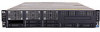
HP ProLiant DL288 HP ProLiant DL288 G6 Server Maintenance and Service Guide - Page 127
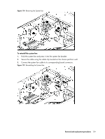
Device number, Connector, To remove the system fan, Power down the server.
 |
View all HP ProLiant DL288 manuals
Add to My Manuals
Save this manual to your list of manuals |
Page 127 highlights
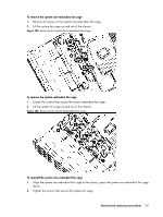
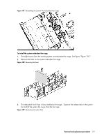
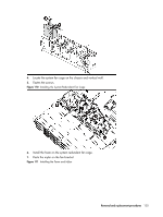
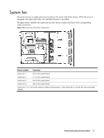
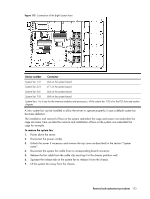
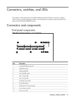
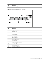
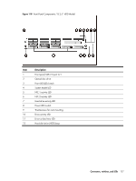
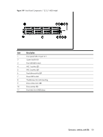
Figure 113 Connection of the Eight System Fans Device number Connector System fan 1/2 J63 on the system board System fan 3/4 J71 on the system board System fan 5/6 J62 on the system board System fan 7/8 J68 on the system board System fans 1 to 6 are for the memory modules and processors, while system fan 7/8 is for the PCI slots and system chipsets. A new system fan can be installed to allow the server to operate properly in case a default system fan becomes defective. The installation and removal of fans on the system redundant fan cage and system non-redundant fan cage are same, here we take the removal and installation of fans on the system non-redundant fan cage for example. To remove the system fan: 1. Power down the server. 2. Disconnect the power cord(s). 3. Unlock the server if necessary and remove the top cover as described in the section "System cover". 4. Disconnect the system fan cable from its corresponding board connector. 5. Release the fan cable from the cable clip securing it to the chassis partition wall. 6. Squeeze the release tab on the system fan to release it from the chassis. 7. Lift the system fan away from the chassis. Removal and replacement procedures 123
-
 1
1 -
2
-
3
-
4
-
5
-
6
-
7
-
8
-
9
-
10
-
11
-
12
-
13
-
14
-
15
-
16
-
17
-
18
-
19
-
20
-
21
-
22
-
23
-
24
-
25
-
26
-
27
-
28
-
29
-
30
-
31
-
32
-
33
-
34
-
35
-
36
-
37
-
38
-
39
-
40
-
41
-
42
-
43
-
44
-
45
-
46
-
47
-
48
-
49
-
50
-
51
-
52
-
53
-
54
-
55
-
56
-
57
-
58
-
59
-
60
-
61
-
62
-
63
-
64
-
65
-
66
-
67
-
68
-
69
-
70
-
71
-
72
-
73
-
74
-
75
-
76
-
77
-
78
-
79
-
80
-
81
-
82
-
83
-
84
-
85
-
86
-
87
-
88
-
89
-
90
-
91
-
92
-
93
-
94
-
95
-
96
-
97
-
98
-
99
-
100
-
101
-
102
-
103
-
104
-
105
-
106
-
107
-
108
-
109
-
110
-
111
-
112
-
113
-
114
-
115
-
116
-
117
-
118
-
119
-
120
-
121
-
 122
122 -
 123
123 -
 124
124 -
 125
125 -
 126
126 -
 127
127 -
 128
128 -
 129
129 -
 130
130 -
 131
131 -
 132
132 -
133
-
134
-
135
-
136
-
137
-
138
-
139
-
140
-
141
-
142
-
143
-
144
-
145
-
146
-
147
-
148
-
149
-
150
-
151
-
152
-
153
-
154
-
155
-
156
-
157
-
158
-
159
-
160
-
161
-
162
-
163
 |
 |
