HP ProLiant DL288 HP ProLiant DL288 G6 Server Maintenance and Service Guide - Page 43
Removal and replacement procedures, Hardware configuration tools, Electrostatic discharge information
 |
View all HP ProLiant DL288 manuals
Add to My Manuals
Save this manual to your list of manuals |
Page 43 highlights
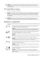
Removal and replacement procedures This chapter provides subassembly/module-level removal and replacement procedures for the HP ProLiant DL288 G6 server. Review the specifications of a new component before installing it to make sure it is compatible with the server. When you integrate new components into the system, record its model and serial number, and any other pertinent information for future reference. After completing any removal or replacement procedure, run the diagnostics program to verify that all components operate properly. NOTE: The figures used in this chapter to illustrate procedural steps are labeled numerically (i.e., 1, 2...). When these figures are used in substep items, the alphabetically labeled instructions correspond to the numbered labels on the related figure (i.e., label 1 corresponds to step a, label 2 corresponds to step b, etc.). The procedures described in this section assume that the server is out of the rack and is positioned on a flat, stable surface. Hardware configuration tools You will need the following tools: • T-10/T-15 wrench The following references and software tools will assist with the hardware configuration: • HP ProLiant DL288 G6 Server Easy set-up CD • IPMI Event Log • Diagnostics Utility Software Hardware configuration information Electrostatic discharge information An electrostatic discharge (ESD) can damage static-sensitive devices or micro circuitry. Proper packaging and grounding techniques are necessary precautions to prevent damage. To prevent electrostatic damage, observe the following precautions: • Transport products in static-safe containers such as conductive tubes, bags, or boxes. • Keep electrostatic-sensitive parts in their containers until they arrive at static-free stations. • Cover workstations with approved static-dissipating material. Use a wrist strap connected to the work surface, and properly grounded (earthed) tools and equipment. • Keep work area free of nonconductive materials, such as ordinary plastic assembly aids and foam packing. • Make sure that you are always properly grounded (earthed) when touching a static-sensitive component or assembly. • Avoid touching pins, leads, or circuitry. • Always place drives with the Printed Circuit Board (PCB) assembly-side down. • Use conductive field service tools. Removal and replacement procedures 39
-
 1
1 -
2
-
3
-
4
-
5
-
6
-
7
-
8
-
9
-
10
-
11
-
12
-
13
-
14
-
15
-
16
-
17
-
18
-
19
-
20
-
21
-
22
-
23
-
24
-
25
-
26
-
27
-
28
-
29
-
30
-
31
-
32
-
33
-
34
-
35
-
36
-
37
-
 38
38 -
 39
39 -
 40
40 -
 41
41 -
 42
42 -
 43
43 -
 44
44 -
 45
45 -
 46
46 -
 47
47 -
 48
48 -
49
-
50
-
51
-
52
-
53
-
54
-
55
-
56
-
57
-
58
-
59
-
60
-
61
-
62
-
63
-
64
-
65
-
66
-
67
-
68
-
69
-
70
-
71
-
72
-
73
-
74
-
75
-
76
-
77
-
78
-
79
-
80
-
81
-
82
-
83
-
84
-
85
-
86
-
87
-
88
-
89
-
90
-
91
-
92
-
93
-
94
-
95
-
96
-
97
-
98
-
99
-
100
-
101
-
102
-
103
-
104
-
105
-
106
-
107
-
108
-
109
-
110
-
111
-
112
-
113
-
114
-
115
-
116
-
117
-
118
-
119
-
120
-
121
-
122
-
123
-
124
-
125
-
126
-
127
-
128
-
129
-
130
-
131
-
132
-
133
-
134
-
135
-
136
-
137
-
138
-
139
-
140
-
141
-
142
-
143
-
144
-
145
-
146
-
147
-
148
-
149
-
150
-
151
-
152
-
153
-
154
-
155
-
156
-
157
-
158
-
159
-
160
-
161
-
162
-
163
 |
 |