HP StorageWorks 2/32 HP StorageWorks SAN Switch 2/32 V4.2.X Installation Guide - Page 24
Cooling Requirements, contains the air intake vents, facing the cool-air aisle.
 |
View all HP StorageWorks 2/32 manuals
Add to My Manuals
Save this manual to your list of manuals |
Page 24 highlights
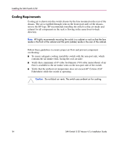
Installing the SAN Switch 2/32 Cooling Requirements Cooling air is drawn into the switch chassis by the fans mounted on the rear of the chassis. The air is expelled through vents in the front (port side) of the chassis, next to the HP logo. HP recommends installing the switch so that air intake and exhaust for all components in the rack is flowing in the same front-to-back direction. Note: HP highly recommends mounting the switch in a cabinet or rack so that the fans reside in the front of the cabinet and the ports (cables) reside in the rear of the cabinet. Follow these guidelines to ensure proper air flow and prevent component overheating: ■ To ensure adequate cooling, install the switch with the non-port side, which contains the air intake vents, facing the cool-air aisle. ■ Verify that a minimum of 47 cubic feet/minute (79.8 cubic meters/hour) of air flow is available to the air intake vents on the non-port side of the switch. ■ Verify that the ambient air temperature does not exceed 40° Celsius (104° Fahrenheit) while the switch is operating. Caution: Do not block air vents. The switch uses ambient air for cooling. 24 SAN Switch 2/32 Version 4.2.x Installation Guide
-
 1
1 -
2
-
3
-
4
-
5
-
6
-
7
-
8
-
9
-
10
-
11
-
12
-
13
-
14
-
15
-
16
-
17
-
18
-
 19
19 -
 20
20 -
 21
21 -
 22
22 -
 23
23 -
 24
24 -
 25
25 -
 26
26 -
 27
27 -
 28
28 -
 29
29 -
30
-
31
-
32
-
33
-
34
-
35
-
36
-
37
-
38
-
39
-
40
-
41
-
42
-
43
-
44
-
45
-
46
-
47
-
48
-
49
-
50
-
51
-
52
-
53
-
54
-
55
-
56
-
57
-
58
-
59
-
60
-
61
-
62
-
63
-
64
-
65
-
66
-
67
-
68
-
69
-
70
-
71
-
72
-
73
-
74
-
75
-
76
-
77
-
78
-
79
-
80
-
81
-
82
-
83
-
84
-
85
-
86
-
87
-
88
-
89
-
90
-
91
-
92
-
93
-
94
-
95
-
96
-
97
-
98
-
99
-
100
 |
 |
