HP StorageWorks 2/32 HP StorageWorks SAN Switch 2/32 V4.2.X Installation Guide - Page 34
Assemble the two inner rails one on each side to the switch using the ten
 |
View all HP StorageWorks 2/32 manuals
Add to My Manuals
Save this manual to your list of manuals |
Page 34 highlights
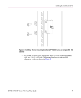
Installing the SAN Switch 2/32 Note: The mounting holes in the inner rails are marked with 32, 16, and 8. When mounting the SAN Switch 2/32, use the mounting holes labelled 32 when installing the inner rails on the switch. When viewing a rack from the front, the left rails are used in the left side of the rack and the right rails are used in the right side of the rack. The rails must match up-right inner with right outer and left inner with left outer. Note that the SAN Switch mounts in the rack with its front, the port side, facing the back of the rack. The rear of the switch, the AC side, faces the front of the rack. 5. Assemble the two inner rails (one on each side) to the switch using the ten #8-32 x 3/16-inch Phillips pan-head screws with thread lock as shown in Figure 9. Note: The rail kit provides fourteen #8-32 x 3/16-inch screws for assembling the inner rails. Each switch requires a different number of these screws. For example, Figure 9 shows an inner rail being attached to the SAN Switch 2/32 with five screws. Attaching both inner rails requires ten screws. 0012a Figure 9: Assembling the inner rails 34 SAN Switch 2/32 Version 4.2.x Installation Guide
-
 1
1 -
2
-
3
-
4
-
5
-
6
-
7
-
8
-
9
-
10
-
11
-
12
-
13
-
14
-
15
-
16
-
17
-
18
-
19
-
20
-
21
-
22
-
23
-
24
-
25
-
26
-
27
-
28
-
 29
29 -
 30
30 -
 31
31 -
 32
32 -
 33
33 -
 34
34 -
 35
35 -
 36
36 -
 37
37 -
 38
38 -
 39
39 -
40
-
41
-
42
-
43
-
44
-
45
-
46
-
47
-
48
-
49
-
50
-
51
-
52
-
53
-
54
-
55
-
56
-
57
-
58
-
59
-
60
-
61
-
62
-
63
-
64
-
65
-
66
-
67
-
68
-
69
-
70
-
71
-
72
-
73
-
74
-
75
-
76
-
77
-
78
-
79
-
80
-
81
-
82
-
83
-
84
-
85
-
86
-
87
-
88
-
89
-
90
-
91
-
92
-
93
-
94
-
95
-
96
-
97
-
98
-
99
-
100
 |
 |
