Lexmark E360d Service Manual - Page 135
Printhead removal, Top cover assembly removal
 |
View all Lexmark E360d manuals
Add to My Manuals
Save this manual to your list of manuals |
Page 135 highlights
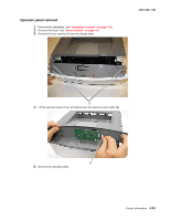
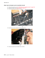
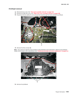
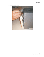
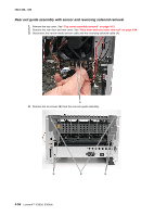
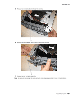
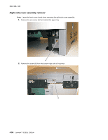
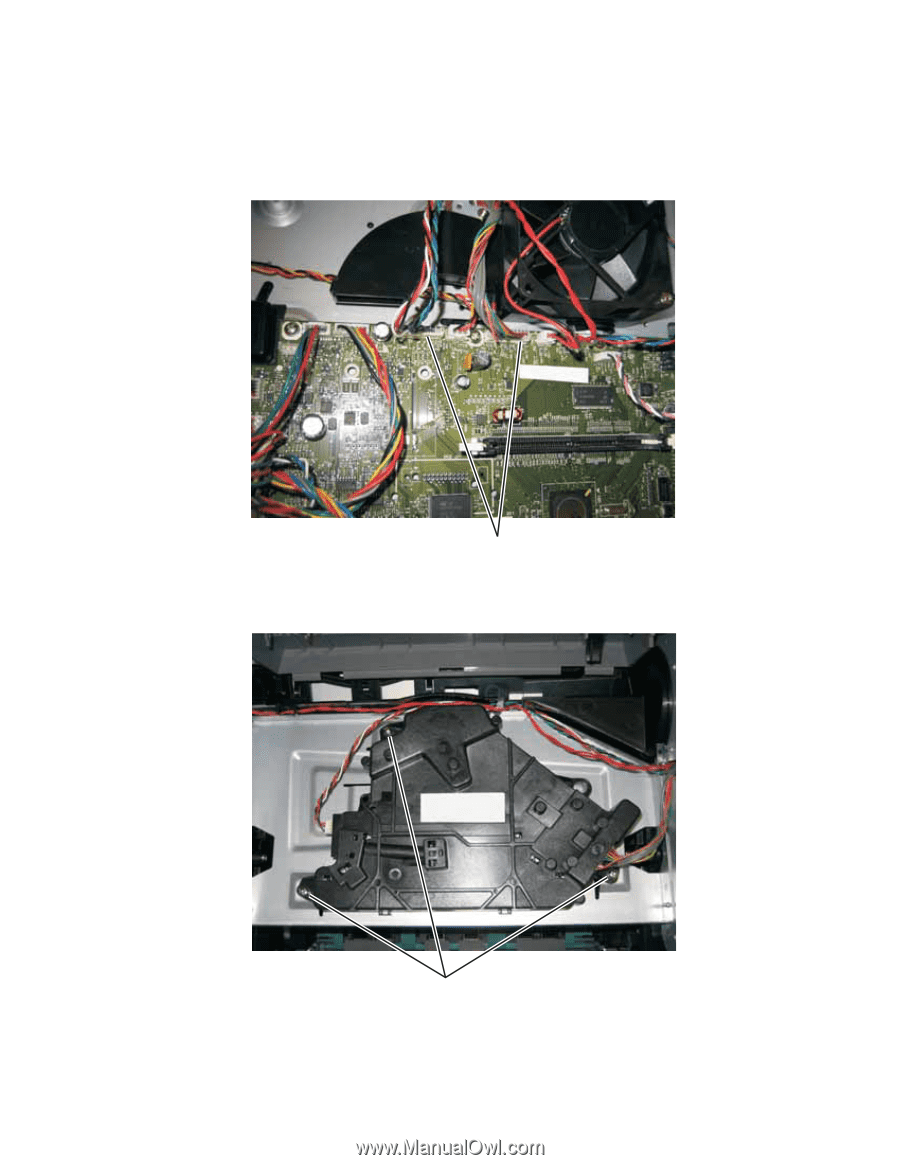
4513-420, -430 Printhead removal 1. Remove the top cover. See "Top cover assembly removal" on page 4-61. 2. Remove the right side cover. See "Right side cover assembly removal" on page 4-58 3. Disconnect the two cables (A), and unroute them back through the frame toward the printhead. A 4. Remove the three screws (B). Note: Use a pencil to mark the screw locations of the printhead on the metal frame. Align the new printhead relative to the location of the old printhead. See "Printhead assembly mechanical adjustment" on page 3-17. B 5. Remove the printhead. Repair information 4-53
-
 1
1 -
2
-
3
-
4
-
5
-
6
-
7
-
8
-
9
-
10
-
11
-
12
-
13
-
14
-
15
-
16
-
17
-
18
-
19
-
20
-
21
-
22
-
23
-
24
-
25
-
26
-
27
-
28
-
29
-
30
-
31
-
32
-
33
-
34
-
35
-
36
-
37
-
38
-
39
-
40
-
41
-
42
-
43
-
44
-
45
-
46
-
47
-
48
-
49
-
50
-
51
-
52
-
53
-
54
-
55
-
56
-
57
-
58
-
59
-
60
-
61
-
62
-
63
-
64
-
65
-
66
-
67
-
68
-
69
-
70
-
71
-
72
-
73
-
74
-
75
-
76
-
77
-
78
-
79
-
80
-
81
-
82
-
83
-
84
-
85
-
86
-
87
-
88
-
89
-
90
-
91
-
92
-
93
-
94
-
95
-
96
-
97
-
98
-
99
-
100
-
101
-
102
-
103
-
104
-
105
-
106
-
107
-
108
-
109
-
110
-
111
-
112
-
113
-
114
-
115
-
116
-
117
-
118
-
119
-
120
-
121
-
122
-
123
-
124
-
125
-
126
-
127
-
128
-
129
-
 130
130 -
 131
131 -
 132
132 -
 133
133 -
 134
134 -
 135
135 -
 136
136 -
 137
137 -
 138
138 -
 139
139 -
 140
140 -
141
-
142
-
143
-
144
-
145
-
146
-
147
-
148
-
149
-
150
-
151
-
152
-
153
-
154
-
155
-
156
-
157
-
158
-
159
-
160
-
161
-
162
-
163
-
164
-
165
-
166
-
167
-
168
-
169
-
170
 |
 |
Repair information
4-53
4513-420, -430
Printhead removal
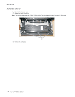
1.
Remove the top cover. See
“Top cover assembly removal” on page 4-61
.
2.
Remove the right side cover. See
“Right side cover assembly removal” on page 4-58
3.
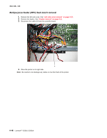
Disconnect the two cables (A), and unroute them back through the frame toward the printhead.
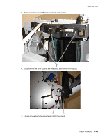
4.
Remove the three screws (B).
Note:
Use a pencil to mark the screw locations of the printhead on the metal frame. Align the new printhead
relative to the location of the old printhead. See
“Printhead assembly mechanical adjustment” on page 3-17
.
5.
Remove the printhead.
A
B