Lexmark E360d Service Manual - Page 49
Cooling fan service check, Cover interlock switch service check - printer cartridge
 |
View all Lexmark E360d manuals
Add to My Manuals
Save this manual to your list of manuals |
Page 49 highlights
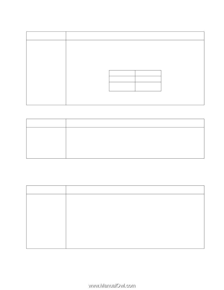
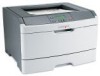
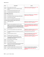
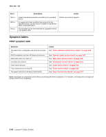
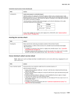
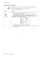
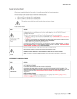
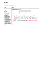
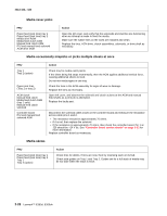
4513-420, -430 Controller board service check (Continued) FRU LVPS/HVPS Action Verify main power to controller board With the printer off, unplug the LPS/HVPS cable at J502 on the controller board. Verify grounds on pins 10, 12, 14, 16 and 18 for both the cable and the controller board. If any of these grounds are incorrect, then check the cable for continuity. If the cable fails continuity, then call the next level of support. Turn the printer on with the cable still unplugged, and verify the following on the cable (controller board will not be powered): Pins Voltage 6, 17, 19 +24 V dc 1, 3-5, 11, 13, +5 V dc 15 If any of the voltages are incorrect, then replace the LVPS/HVPS. See "Dead machine service check" on page 2-24. Cooling fan service check FRU Cooling fan Action Make sure the fan cable plug is properly seated at J9 (controller board). Turn the printer on. Within a few seconds, the controller board assembly should apply +24 V dc to pin 2. • If voltage is not present, then check or replace the controller board. See "Controller board removal" on page 4-6. • If voltage is present, then check pin 1 for 24 V dc as well. If it is close to 24 V dc while the fan is still idle, then replace the fan. See "Fan removal" on page 4-16. Cover interlock switch service check Note: Make sure a print cartridge assembly is installed and the cover closes all the way, engaging the cover open switch lever. FRU Cover interlock switch Action Disconnect the cover interlock cable from the controller board at J7. With the printer turned off: 1. Verify continuity between cable pin 1 and pin 2 with the door closed and discontinuity with the door open. 2. Verify continuity between cable pin 1 and pin 3 with the door open and discontinuity with the door closed. 3. Verify discontinuity between cable pins 2 and 3 whether the door is open or closed. • If any fail, then replace the cover interlock switch. • If both pass continuity, then turn the printer on, and measure +5 V dc on pin 2 at J7 on the controller board. • Verify pin 3 at J7 is ground. • If voltage or ground is not present, then see "Controller board service check" on page 2-22 for more information. Diagnostics information 2-23
-
 1
1 -
2
-
3
-
4
-
5
-
6
-
7
-
8
-
9
-
10
-
11
-
12
-
13
-
14
-
15
-
16
-
17
-
18
-
19
-
20
-
21
-
22
-
23
-
24
-
25
-
26
-
27
-
28
-
29
-
30
-
31
-
32
-
33
-
34
-
35
-
36
-
37
-
38
-
39
-
40
-
41
-
42
-
43
-
 44
44 -
 45
45 -
 46
46 -
 47
47 -
 48
48 -
 49
49 -
 50
50 -
 51
51 -
 52
52 -
 53
53 -
 54
54 -
55
-
56
-
57
-
58
-
59
-
60
-
61
-
62
-
63
-
64
-
65
-
66
-
67
-
68
-
69
-
70
-
71
-
72
-
73
-
74
-
75
-
76
-
77
-
78
-
79
-
80
-
81
-
82
-
83
-
84
-
85
-
86
-
87
-
88
-
89
-
90
-
91
-
92
-
93
-
94
-
95
-
96
-
97
-
98
-
99
-
100
-
101
-
102
-
103
-
104
-
105
-
106
-
107
-
108
-
109
-
110
-
111
-
112
-
113
-
114
-
115
-
116
-
117
-
118
-
119
-
120
-
121
-
122
-
123
-
124
-
125
-
126
-
127
-
128
-
129
-
130
-
131
-
132
-
133
-
134
-
135
-
136
-
137
-
138
-
139
-
140
-
141
-
142
-
143
-
144
-
145
-
146
-
147
-
148
-
149
-
150
-
151
-
152
-
153
-
154
-
155
-
156
-
157
-
158
-
159
-
160
-
161
-
162
-
163
-
164
-
165
-
166
-
167
-
168
-
169
-
170
 |
 |