Lexmark E360d Service Manual - Page 53
Operator panel service check, Paper feed service checks, Paper jam error indication during POST
 |
View all Lexmark E360d manuals
Add to My Manuals
Save this manual to your list of manuals |
Page 53 highlights
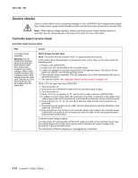
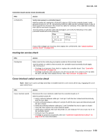
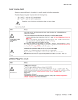
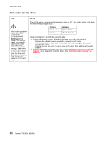
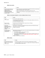
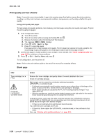
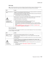
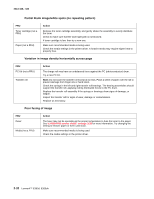
4513-420, -430 Operator panel service check Inspect the operator panel cable for damage. Make sure the cable is plugged in securely. Run POST, and check each light for proper operation. See "Power-On Self Test (POST) sequence" on page 2-1. LCD Operator panel service check FRU Operator panel (LCD) Controller board Warning: Do not replace the operator panel and controller board at the same time. Each card contains the printer settings. When either of these cards is new, it obtains the settings from the other card. Settings are lost when both are new and replaced at the same time. Action Lights If the LCD does not come on, then open the controller board cage and locate the operator panel connector at J3. Make sure the cable is properly connected to the controller board and the controller board has input voltage to it. With the printer on, verify the following without disconnecting the cable: • Pins 1, 3, 5, and 6: 3.3 v • Pin 2: 5 v • Pins 4 and 7: GND If these are approximately correct and the operator panel is not functioning, then replace the operator panel. If any are incorrect, then see "Controller board service check" on page 2-22. Buttons If the buttons do not respond, then replace the operator panel. There is no test or repair for the faulty switches on the operator panel. Paper feed service checks Paper jam error indication during POST FRU Fuser (exit sensor) Input/duplex sensor Manual feed sensor Action If the exit sensor flag, which is visible at the back of the fuser, is in any position other than vertical, then the printer will display a paper jam. Make sure the flag is operating freely. Replace the fuser if the sensor is damaged. Make sure the input paper feed sensors are working properly. A stuck or incorrectly installed sensor causes a paper jam indication. Media picks but stops halfway through the printer FRU Input/duplex sensors (under print cartridge assembly) Input sensor (manual) Action Make sure the input sensors are working properly. Check for a broken or stuck flag on the input sensors. Clear anything that keeps the flags from rotating freely. Make sure the cables are seated on the controller board at J27 (input/duplex sensor) and J23 (manual input). Check for +5 V dc on pin 2 and 5 at J27 (input/duplex sensors) and pin 2 at J23 (Input sensor). Voltages on pins 1 and 4 at J27 pin 1 at &23 should change as the flags intersect with the sensor. • If correct, then replace the input paper feed sensor. • If these voltages are not correct, then replace the controller board. • Check the pick tires. Clean or replace as necessary. Diagnostics information 2-27
-
 1
1 -
2
-
3
-
4
-
5
-
6
-
7
-
8
-
9
-
10
-
11
-
12
-
13
-
14
-
15
-
16
-
17
-
18
-
19
-
20
-
21
-
22
-
23
-
24
-
25
-
26
-
27
-
28
-
29
-
30
-
31
-
32
-
33
-
34
-
35
-
36
-
37
-
38
-
39
-
40
-
41
-
42
-
43
-
44
-
45
-
46
-
47
-
 48
48 -
 49
49 -
 50
50 -
 51
51 -
 52
52 -
 53
53 -
 54
54 -
 55
55 -
 56
56 -
 57
57 -
 58
58 -
59
-
60
-
61
-
62
-
63
-
64
-
65
-
66
-
67
-
68
-
69
-
70
-
71
-
72
-
73
-
74
-
75
-
76
-
77
-
78
-
79
-
80
-
81
-
82
-
83
-
84
-
85
-
86
-
87
-
88
-
89
-
90
-
91
-
92
-
93
-
94
-
95
-
96
-
97
-
98
-
99
-
100
-
101
-
102
-
103
-
104
-
105
-
106
-
107
-
108
-
109
-
110
-
111
-
112
-
113
-
114
-
115
-
116
-
117
-
118
-
119
-
120
-
121
-
122
-
123
-
124
-
125
-
126
-
127
-
128
-
129
-
130
-
131
-
132
-
133
-
134
-
135
-
136
-
137
-
138
-
139
-
140
-
141
-
142
-
143
-
144
-
145
-
146
-
147
-
148
-
149
-
150
-
151
-
152
-
153
-
154
-
155
-
156
-
157
-
158
-
159
-
160
-
161
-
162
-
163
-
164
-
165
-
166
-
167
-
168
-
169
-
170
 |
 |