Lexmark E360d Service Manual - Page 151
-430, Connector, Value, cable plugged, if different, Comments, Open door sensor
 |
View all Lexmark E360d manuals
Add to My Manuals
Save this manual to your list of manuals |
Page 151 highlights
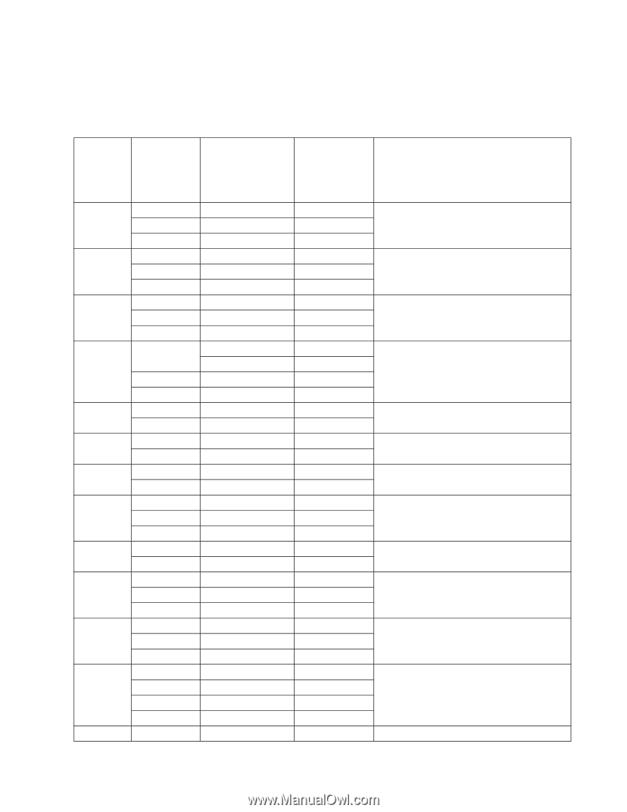
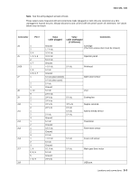
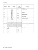
4513-420, -430 Note: See the wiring diagram at back of book. These values were measured with all connections made (plugged) or with only one connector at a time unplugged to expose the pins. Always disconnect and connect with the printer power off. Otherwise, the values below may not match. Connector Pin # J4 J5 J100 J7 J8 J9 J10 J11 J12 J13 J14 J17 J19 1 2 3, 4 1, 3, 5, 6 2 4, 7 1 2, 3 4, 5, 6, 7 1 2 3 1, 10 9 1 2 1 2 1 2 3 1 2 1 2 3 1 2 3 1, 4 2, 3, 6 5 7, 8, 9 Value cable plugged Value cable unplugged (if different) Comments Ground 1.7 V dc Cartridge (The front access door must be closed.) 3.3 V dc 3.3 V dc Operator panel 5.0 V dc Ground > 0 V dc 5 V dc 5 V dc Printhead Ground 5 V dc (door closed) Open door sensor 0 V dc (door open) 5 V dc Ground 5 V dc LSU 2.9 V dc 24 V dc 0 V dc Cooling fan 24 V dc 24 V dc 24 V dc Duplex solenoid 24 V dc 0 V dc 5 V dc Narrow media sensor 5 V dc 5 V dc Ground 5 V dc Thermistor Ground 0.6 V dc Ground Toner level sensor 0 V dc > 0 V dc 5 V dc Fuser exit sensor 5 V dc Ground 0.1 V dc 5 V dc Main gear drive motor 5 V dc Ground 24 V dc USB port Locations and connections 5-3
-
 1
1 -
2
-
3
-
4
-
5
-
6
-
7
-
8
-
9
-
10
-
11
-
12
-
13
-
14
-
15
-
16
-
17
-
18
-
19
-
20
-
21
-
22
-
23
-
24
-
25
-
26
-
27
-
28
-
29
-
30
-
31
-
32
-
33
-
34
-
35
-
36
-
37
-
38
-
39
-
40
-
41
-
42
-
43
-
44
-
45
-
46
-
47
-
48
-
49
-
50
-
51
-
52
-
53
-
54
-
55
-
56
-
57
-
58
-
59
-
60
-
61
-
62
-
63
-
64
-
65
-
66
-
67
-
68
-
69
-
70
-
71
-
72
-
73
-
74
-
75
-
76
-
77
-
78
-
79
-
80
-
81
-
82
-
83
-
84
-
85
-
86
-
87
-
88
-
89
-
90
-
91
-
92
-
93
-
94
-
95
-
96
-
97
-
98
-
99
-
100
-
101
-
102
-
103
-
104
-
105
-
106
-
107
-
108
-
109
-
110
-
111
-
112
-
113
-
114
-
115
-
116
-
117
-
118
-
119
-
120
-
121
-
122
-
123
-
124
-
125
-
126
-
127
-
128
-
129
-
130
-
131
-
132
-
133
-
134
-
135
-
136
-
137
-
138
-
139
-
140
-
141
-
142
-
143
-
144
-
145
-
 146
146 -
 147
147 -
 148
148 -
 149
149 -
 150
150 -
 151
151 -
 152
152 -
 153
153 -
 154
154 -
 155
155 -
 156
156 -
157
-
158
-
159
-
160
-
161
-
162
-
163
-
164
-
165
-
166
-
167
-
168
-
169
-
170
 |
 |