Lexmark E360d Service Manual - Page 64
Tray 2 service check, Pin 2: 24 V - e360dn printer manual
 |
View all Lexmark E360d manuals
Add to My Manuals
Save this manual to your list of manuals |
Page 64 highlights
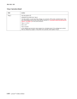
4513-420, -430 Tray 2 service check FRU Tray 2 Action Turn the printer off. Separate the printer from Tray 2. Turn the printer on and check the voltages on connector J28 on the controller board. See the wiring diagram at the end of the service manual, or "Controller board connector pin values" on page 3-2 for the J28 connector. Pins 1, 4: 3.3 V Pin 2: 24 V Pin 6: Ground If the voltages are incorrent, then replace the controller board. If the voltages are correct, then try using Tray 2 again. If the printer error persists, then replace Tray 2. 2-38 Lexmark™ E360d, E360dn
-
 1
1 -
2
-
3
-
4
-
5
-
6
-
7
-
8
-
9
-
10
-
11
-
12
-
13
-
14
-
15
-
16
-
17
-
18
-
19
-
20
-
21
-
22
-
23
-
24
-
25
-
26
-
27
-
28
-
29
-
30
-
31
-
32
-
33
-
34
-
35
-
36
-
37
-
38
-
39
-
40
-
41
-
42
-
43
-
44
-
45
-
46
-
47
-
48
-
49
-
50
-
51
-
52
-
53
-
54
-
55
-
56
-
57
-
58
-
 59
59 -
 60
60 -
 61
61 -
 62
62 -
 63
63 -
 64
64 -
 65
65 -
 66
66 -
 67
67 -
 68
68 -
 69
69 -
70
-
71
-
72
-
73
-
74
-
75
-
76
-
77
-
78
-
79
-
80
-
81
-
82
-
83
-
84
-
85
-
86
-
87
-
88
-
89
-
90
-
91
-
92
-
93
-
94
-
95
-
96
-
97
-
98
-
99
-
100
-
101
-
102
-
103
-
104
-
105
-
106
-
107
-
108
-
109
-
110
-
111
-
112
-
113
-
114
-
115
-
116
-
117
-
118
-
119
-
120
-
121
-
122
-
123
-
124
-
125
-
126
-
127
-
128
-
129
-
130
-
131
-
132
-
133
-
134
-
135
-
136
-
137
-
138
-
139
-
140
-
141
-
142
-
143
-
144
-
145
-
146
-
147
-
148
-
149
-
150
-
151
-
152
-
153
-
154
-
155
-
156
-
157
-
158
-
159
-
160
-
161
-
162
-
163
-
164
-
165
-
166
-
167
-
168
-
169
-
170
 |
 |
2-38
Lexmark™ E360d, E360dn
4513-420, -430
Tray 2 service check
FRU
Action
Tray 2
Turn the printer off.
Separate the printer from Tray 2.
Turn the printer on and check the voltages on connector J28 on the controller board. See
the wiring diagram at the end of the service manual, or
“Controller board connector pin
values” on page 3-2
for the J28 connector.
Pins 1, 4: 3.3 V
Pin 2: 24 V
Pin 6: Ground
If the voltages are incorrent, then replace the controller board. If the voltages are correct,
then try using Tray 2 again. If the printer error persists, then replace Tray 2.