Panasonic DMREZ485V Dvd Recorder - English/spanish - Page 8
Basic Connection, Connecting to a Television with Direct Cable or Antenna No Cable Box or Satellite
 |
View all Panasonic DMREZ485V manuals
Add to My Manuals
Save this manual to your list of manuals |
Page 8 highlights
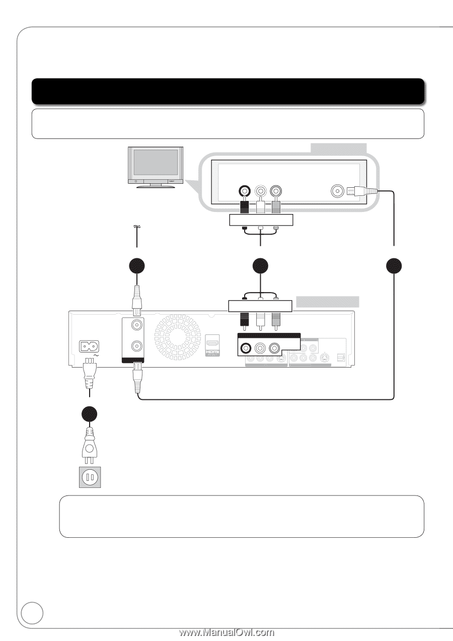
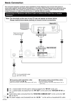
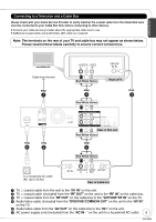
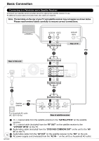
Basic Connection The connection diagrams represent typical installations. These diagrams may not work with certain inhouse cable systems, master antenna installations, or situations where TV programming is delivered using methods that differ from industry accepted practices. If you require assistance with connections, please contact Panasonic at 1-800-211-7262 (for U.S.A.) or 1-800-561-5505 (for Canada). Connecting to a Television with Direct Cable or Antenna (No Cable Box or Satellite Receiver) Note: The terminals on the rear of your TV may not appear as shown below. Please read terminal labels carefully to ensure correct connections. Rear of TV AUDIO IN VIDEO R L IN VHF/UHF RF IN Cable from the wall or antenna signal Red White Yellow step step step 1 3 2 AC IN RF IN RF OUT VHF / UHF Red White Yellow Rear of this unit DVD/VHS COMMON OUT R-AUDDVIDO/V-HLS COMVMOIDNEOOUT R-AUDIO-L VIDEO COMPONENT VIDEO OUT Y PB PR S VIDEO S VIDEO R-AUDIO -L VIDEO IN1 R-AUDIO-L VIDEO DVD PRIORITY OUT OPTICAL DIGITAL AUDIO OUT (PCM/BITSTREAM) step 4 To a household AC outlet (AC 120 V, 60 Hz) Connection (with Audio/Video cable) Connect in numbered order to . After this connection, set the RF output channel "OFF" ( 12). Connection (without Audio/Video cable) You do not need to connect . After this connection, set the RF output channel "CH3" or "CH4" ( 12). 75 coaxial cable from the wall or antenna signal to the "RF IN" on the unit. 75 coaxial cable (included) from the "RF OUT" on the unit to the "VHF/UHF RF IN" on the TV. Audio/video cable (included) from the "DVD/VHS COMMON OUT" on the unit to the "AV IN" on the TV. 8 AC power supply cord (included) from the "AC IN" on the unit to a household AC outlet. RQT9056
-
 1
1 -
2
-
 3
3 -
 4
4 -
 5
5 -
 6
6 -
 7
7 -
 8
8 -
 9
9 -
 10
10 -
 11
11 -
 12
12 -
 13
13 -
14
-
15
-
16
-
17
-
18
-
19
-
20
-
21
-
22
-
23
-
24
-
25
-
26
-
27
-
28
-
29
-
30
-
31
-
32
-
33
-
34
-
35
-
36
-
37
-
38
-
39
-
40
-
41
-
42
-
43
-
44
-
45
-
46
-
47
-
48
-
49
-
50
-
51
-
52
-
53
-
54
-
55
-
56
-
57
-
58
-
59
-
60
-
61
-
62
-
63
-
64
-
65
-
66
-
67
-
68
-
69
-
70
-
71
-
72
-
73
-
74
-
75
-
76
-
77
-
78
-
79
-
80
-
81
-
82
-
83
-
84
-
85
-
86
-
87
-
88
-
89
-
90
-
91
-
92
-
93
-
94
-
95
-
96
-
97
-
98
-
99
-
100
 |
 |