Canon PowerShot 350 Service Manual - Page 34
Camera, Block, Diagram
 |
View all Canon PowerShot 350 manuals
Add to My Manuals
Save this manual to your list of manuals |
Page 34 highlights
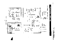
Part 2: Technical Information 1.2 CAMERA BLOCK DIAGRAM Lens unit C -Flash Block IRIS-A IRIS-B Camera CBA CCD (1/3" VGA) CCD OUT 4) R (pH H-Driver .4 H, V-Driver V, SUB, CH1 ST1 Light metering Light metering Sensor Circuit Flash Flash Charge Circuit STR-TRG STO ST1 CDS, AGS II.O AD IN A DS1, DS2, CPOB, PBLK, CP2 A 1 I CG A HD VD3 CGDATA CGSCK EXFCK 2FCK BUFFER OSC 0 24.54 MHz I-I EVR AGC, PEDE, AD APA, OB, KNEE RBIAS, V-SUB, LC O REC(L) O IRIS-A IRIS-B EVR 0 (SERIAL) >co >0 a2C., «02 > 0 0 2 >co 2 0 a >c9 a 2 0 o z 0 Fig. 2-2 Camera Block The "Camera" block (section) includes the lens aperture diaphragm and its IRIS drive and control circuits. the CCD, CCD Driver, the analog video processor which processes the CCD OUT signal. It also has the system clock generating oscillator (OSC) which is used to develop all the clock pulses in CG. The automatic flash system is also a part of the "Camera" block. The IRIS control within the lens unit is controlled by two signals, IRIS-A and ISIS-B to provide two aperture settings, f/8 (actually f/7 + ND25) and f/2.8 respectively. 2-2
-
 1
1 -
2
-
3
-
4
-
5
-
6
-
7
-
8
-
9
-
10
-
11
-
12
-
13
-
14
-
15
-
16
-
17
-
18
-
19
-
20
-
21
-
22
-
23
-
24
-
25
-
26
-
27
-
28
-
 29
29 -
 30
30 -
 31
31 -
 32
32 -
 33
33 -
 34
34 -
 35
35 -
 36
36 -
 37
37 -
 38
38 -
 39
39 -
40
-
41
-
42
-
43
-
44
-
45
-
46
-
47
-
48
-
49
-
50
-
51
-
52
-
53
-
54
-
55
-
56
-
57
-
58
-
59
-
60
-
61
-
62
-
63
-
64
-
65
-
66
-
67
-
68
-
69
-
70
-
71
-
72
-
73
-
74
-
75
-
76
-
77
-
78
-
79
-
80
-
81
-
82
-
83
-
84
-
85
-
86
-
87
-
88
-
89
-
90
-
91
-
92
-
93
-
94
-
95
-
96
-
97
-
98
-
99
-
100
-
101
-
102
-
103
-
104
-
105
-
106
-
107
-
108
-
109
-
110
-
111
-
112
-
113
-
114
-
115
-
116
-
117
-
118
-
119
-
120
-
121
-
122
-
123
-
124
-
125
-
126
-
127
-
128
-
129
-
130
-
131
-
132
-
133
-
134
-
135
-
136
-
137
-
138
-
139
 |
 |
