Canon PowerShot 350 Service Manual - Page 51
Preparation, Repair
 |
View all Canon PowerShot 350 manuals
Add to My Manuals
Save this manual to your list of manuals |
Page 51 highlights
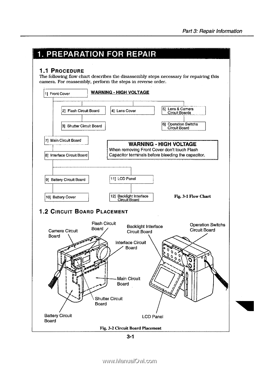
Part3:Repair Information 1. PREPARATION FOR REPAIR 1.1 PROCEDURE The following flow chart describes the disassembly steps necessary for repairing this camera. For reassembly, perform the steps in reverse order. 1] Front Cover WARNING - HIGH VOLTAGE 2] Flash Circuit Board 4] Lens Cover 3] Shutter Circuit Board 5] Lens & Camera Circuit Boards 6] Operation Switchs Circuit Board 7] Main Circuit Board 8] Interface Circuit Board WARNING - HIGH VOLTAGE When removing Front Cover don't touch Flash Capacitor terminals before bleeding the capacitor. 9] Battery Circuit Board 111 LCD Panel 10] Battery Cover 12] Backlight Interface Circuit Board 1.2 CIRCUIT BOARD PLACEMENT Camera Circuit Board Flash Circuit Board Backlight Interface Circuit Board Interface Circuit Board Fig. 3-1 Flow Chart Operation Switchs Circuit Board VJ 41 0 It e Main Circuit / 41" Board II • Shutter Circuit Board Battery Circuit Board LCD Panel Fig. 3-2 Circuit Board Placement 3-1
-
 1
1 -
2
-
3
-
4
-
5
-
6
-
7
-
8
-
9
-
10
-
11
-
12
-
13
-
14
-
15
-
16
-
17
-
18
-
19
-
20
-
21
-
22
-
23
-
24
-
25
-
26
-
27
-
28
-
29
-
30
-
31
-
32
-
33
-
34
-
35
-
36
-
37
-
38
-
39
-
40
-
41
-
42
-
43
-
44
-
45
-
 46
46 -
 47
47 -
 48
48 -
 49
49 -
 50
50 -
 51
51 -
 52
52 -
 53
53 -
 54
54 -
 55
55 -
 56
56 -
57
-
58
-
59
-
60
-
61
-
62
-
63
-
64
-
65
-
66
-
67
-
68
-
69
-
70
-
71
-
72
-
73
-
74
-
75
-
76
-
77
-
78
-
79
-
80
-
81
-
82
-
83
-
84
-
85
-
86
-
87
-
88
-
89
-
90
-
91
-
92
-
93
-
94
-
95
-
96
-
97
-
98
-
99
-
100
-
101
-
102
-
103
-
104
-
105
-
106
-
107
-
108
-
109
-
110
-
111
-
112
-
113
-
114
-
115
-
116
-
117
-
118
-
119
-
120
-
121
-
122
-
123
-
124
-
125
-
126
-
127
-
128
-
129
-
130
-
131
-
132
-
133
-
134
-
135
-
136
-
137
-
138
-
139
 |
 |