Canon PowerShot 350 Service Manual - Page 6
Contents
 |
View all Canon PowerShot 350 manuals
Add to My Manuals
Save this manual to your list of manuals |
Page 6 highlights
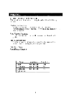
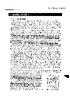
CONTENTS Part 1 General Information 1. INTRODUCTION 1.1 Digital Imaging 1.2 High Image Quality 2. PRODUCT OUTLINE 2.1 Design Concept 2.2 External View 2.3 Nomenclature 2.4 Functions and Operations 2.5 Flash 2.6 Exposure Compensation 2.7 White Balance 2.8 Self-Timer Mode 2.9 "Negative" Mode 2.10 Multi-image Mode 2.11 Erasing Images 2.12 Low Battery Indicator 2.13 CF Card Warning Indicator 2.14 Personal Computer Conniction Indicator 3. SPECIFICATIONS 4. SYSTEM 4.1 System Components and Ancillaries 4.2 Standard & Optional Equipment 4.3 Computer Connection 5. GLOSSARY OF TERMS 5.1 Major Camera Terminology 5.2 Major Software Terminology 5.3 Fixed-Focus and Auto-Focus Part 2 Technical Information 1. ELECTRICAL CIRCUITS 1.1 Overall Block Diagram 1.2 Camera Block Diagram 1.3 CCD and Associated Circuits 1.4 Flash System Block 1.5 Digital Block 1.6 Data Compression Circuits 1.7 ASIC Internal & Associated Circuits 1.8 Power Block 2. IC PIN CONNECTIONS 3. COMMUNICATION WITH PC 3.1 PC Cable 3.2 Connection to Various Operating Systems 4. FILE SHARING WITH POWERSHOT 600 4.1 PowerShot 600 Image Playback Restrictions 4.2 PowerShot 600 Image Playback Operation II 1-1 1-1 1-2 1-3 1-3 1-4 1-5 1-6 1-7 1-7 1-7 1-8 1-8 1-8 1-9 1-10 1-10 1-10 1-11 1-14 1-14 1-15 1-16 1-17 1-17 1-18 1-19 2-1 2-1 2-2 2-3 2-4 2-5 2-6 2-7 2-8 2-9 2-14 2.14 2-14 2-15 2-15 2-15
-
 1
1 -
 2
2 -
 3
3 -
 4
4 -
 5
5 -
 6
6 -
 7
7 -
 8
8 -
 9
9 -
 10
10 -
 11
11 -
 12
12 -
13
-
14
-
15
-
16
-
17
-
18
-
19
-
20
-
21
-
22
-
23
-
24
-
25
-
26
-
27
-
28
-
29
-
30
-
31
-
32
-
33
-
34
-
35
-
36
-
37
-
38
-
39
-
40
-
41
-
42
-
43
-
44
-
45
-
46
-
47
-
48
-
49
-
50
-
51
-
52
-
53
-
54
-
55
-
56
-
57
-
58
-
59
-
60
-
61
-
62
-
63
-
64
-
65
-
66
-
67
-
68
-
69
-
70
-
71
-
72
-
73
-
74
-
75
-
76
-
77
-
78
-
79
-
80
-
81
-
82
-
83
-
84
-
85
-
86
-
87
-
88
-
89
-
90
-
91
-
92
-
93
-
94
-
95
-
96
-
97
-
98
-
99
-
100
-
101
-
102
-
103
-
104
-
105
-
106
-
107
-
108
-
109
-
110
-
111
-
112
-
113
-
114
-
115
-
116
-
117
-
118
-
119
-
120
-
121
-
122
-
123
-
124
-
125
-
126
-
127
-
128
-
129
-
130
-
131
-
132
-
133
-
134
-
135
-
136
-
137
-
138
-
139
 |
 |
