Canon PowerShot 350 Service Manual - Page 57
Removal, Backlight, Circuit, Board
 |
View all Canon PowerShot 350 manuals
Add to My Manuals
Save this manual to your list of manuals |
Page 57 highlights
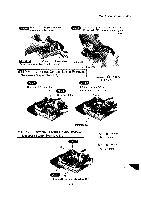
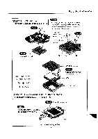
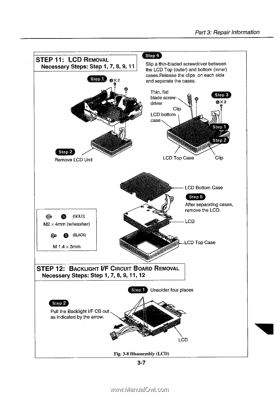
Part 3: Repair Information STEP 11: LCD REMOVAL Necessary Steps: Step 1, 7, 8, 9, 11 Ste 4 Slip a thin-bladed screwdriver between the LCD Top (outer) and bottom (inner) cases.Release the clips on each side and separate the cases. Thin, flat blade screwdriver Clip LCD bottom case Remove LCD Unit LCD Top Case Clip 0 ou (GOLD) M2 x 4mm (w/washer) 0 (BLACK) M 1.4 x3mm LCD Bottom Case Step 5 After separating cases, remove the LCD. LCD LCD Top Case STEP 12: BACKLIGHT I/F CIRCUIT BOARD REMOVAL Necessary Steps: Step 1, 7, 8, 9, 11, 12 Step 2 Pull the Backlight I/F CB out as indicated by the arrow. Step 1 Unsolder four places Fig. 3-8 Disassembly (LCD) 3-7
-
 1
1 -
2
-
3
-
4
-
5
-
6
-
7
-
8
-
9
-
10
-
11
-
12
-
13
-
14
-
15
-
16
-
17
-
18
-
19
-
20
-
21
-
22
-
23
-
24
-
25
-
26
-
27
-
28
-
29
-
30
-
31
-
32
-
33
-
34
-
35
-
36
-
37
-
38
-
39
-
40
-
41
-
42
-
43
-
44
-
45
-
46
-
47
-
48
-
49
-
50
-
51
-
 52
52 -
 53
53 -
 54
54 -
 55
55 -
 56
56 -
 57
57 -
 58
58 -
 59
59 -
 60
60 -
 61
61 -
 62
62 -
63
-
64
-
65
-
66
-
67
-
68
-
69
-
70
-
71
-
72
-
73
-
74
-
75
-
76
-
77
-
78
-
79
-
80
-
81
-
82
-
83
-
84
-
85
-
86
-
87
-
88
-
89
-
90
-
91
-
92
-
93
-
94
-
95
-
96
-
97
-
98
-
99
-
100
-
101
-
102
-
103
-
104
-
105
-
106
-
107
-
108
-
109
-
110
-
111
-
112
-
113
-
114
-
115
-
116
-
117
-
118
-
119
-
120
-
121
-
122
-
123
-
124
-
125
-
126
-
127
-
128
-
129
-
130
-
131
-
132
-
133
-
134
-
135
-
136
-
137
-
138
-
139
 |
 |
Part
3:
Repair
Information
STEP
11:
LCD
REMOVAL
Necessary
Steps:
Step
1,
7,
8,
9,
11
Remove
LCD
Unit
ou
0
(GOLD)
M2
x
4mm
(w/washer)
0
(BLACK)
M
1.4
x3mm
Ste
4
Slip
a
thin
-bladed
screwdriver
between
the
LCD
Top
(outer)
and
bottom
(inner)
cases.Release
the
clips
on
each
side
and
separate
the
cases.
Thin,
flat
blade
screw-
driver
Clip
LCD
bottom
case
LCD
Top
Case
Clip
LCD
Bottom
Case
Step
5
After
separating
cases,
remove
the
LCD.
LCD
LCD
Top
Case
STEP
12:
BACKLIGHT
I/F
CIRCUIT
BOARD
REMOVAL
Necessary
Steps:
Step
1,
7,
8,
9,
11,
12
Step
1
Step
2
Pull
the
Backlight
I/F
CB
out
as
indicated
by
the
arrow.
Unsolder
four
places
Fig.
3-8
Disassembly
(LCD)
3-7