Canon PowerShot 350 Service Manual - Page 56
Battery, Cover, Removal
 |
View all Canon PowerShot 350 manuals
Add to My Manuals
Save this manual to your list of manuals |
Page 56 highlights
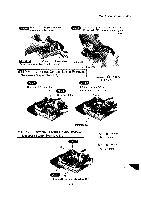
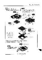
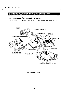
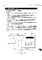
Part 3: Repair Information Step 3 Remove Battery Holder. Step 4 Remove Cover Screw Remove Tripod Socke Step Remove Left Chassis Plate it step 7 QX 2 a CAUTION Battery Holder Installation Step 8 Step 5 Remove Battery CB e ) (BLACK) M 1.4 x3mm e (BLACK) M 1.6 x 4mm • When reinstalling the Battery Holder, insure that the arms on the three switches correctly couple with the switch knobs, which should be in the up position. 4 Switch Knob STEP 10: BATTERY COVER REMOVAL Necessary Steps: Step 1, 7, 8, 9, 10 Step 1 Unlock the claw, and remove the Battery Cover. Claw t. Battery Cove Fig. 3-7 Disassembly (Battery Cover) 3-6 Switch arm Switch Knob
-
 1
1 -
2
-
3
-
4
-
5
-
6
-
7
-
8
-
9
-
10
-
11
-
12
-
13
-
14
-
15
-
16
-
17
-
18
-
19
-
20
-
21
-
22
-
23
-
24
-
25
-
26
-
27
-
28
-
29
-
30
-
31
-
32
-
33
-
34
-
35
-
36
-
37
-
38
-
39
-
40
-
41
-
42
-
43
-
44
-
45
-
46
-
47
-
48
-
49
-
50
-
 51
51 -
 52
52 -
 53
53 -
 54
54 -
 55
55 -
 56
56 -
 57
57 -
 58
58 -
 59
59 -
 60
60 -
 61
61 -
62
-
63
-
64
-
65
-
66
-
67
-
68
-
69
-
70
-
71
-
72
-
73
-
74
-
75
-
76
-
77
-
78
-
79
-
80
-
81
-
82
-
83
-
84
-
85
-
86
-
87
-
88
-
89
-
90
-
91
-
92
-
93
-
94
-
95
-
96
-
97
-
98
-
99
-
100
-
101
-
102
-
103
-
104
-
105
-
106
-
107
-
108
-
109
-
110
-
111
-
112
-
113
-
114
-
115
-
116
-
117
-
118
-
119
-
120
-
121
-
122
-
123
-
124
-
125
-
126
-
127
-
128
-
129
-
130
-
131
-
132
-
133
-
134
-
135
-
136
-
137
-
138
-
139
 |
 |

Part
3:
Repair
Information
Step
Step
3
Remove
Cover
Screw
CAUTION
Remove
Battery
Holder.
Step
4
Remove
Left
Chassis
Plate
Remove
Tripod
Socke
step
7
a
Battery
Holder
Installation
i
t
QX
2
Step
8
Remove
Battery
CB
Step
5
)
e
(BLACK)
M
1.4
x3mm
e
(BLACK)
M
1.6
x
4mm
•
When
reinstalling
the
Battery
Holder,
insure
that
the
arms
on
the
three
switch-
es
correctly
couple
with
the
switch
knobs,
which
should
be
in
the
up
position.
4
Switch
Knob
STEP
10:
BATTERY
COVER
REMOVAL
Necessary
Steps:
Step
1,
7,
8,
9,
10
Step
1
Unlock
the
claw,
and
remove
the
Battery
Cover.
Claw
Switch
arm
Switch
Knob
t
.
Battery
Cove
Fig.
3-7
Disassembly
(Battery
Cover)
3-6