Canon PowerShot 350 Service Manual - Page 44
IC3002, Mi-COM
 |
View all Canon PowerShot 350 manuals
Add to My Manuals
Save this manual to your list of manuals |
Page 44 highlights
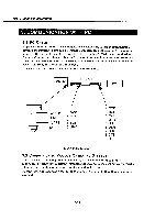
Part 2: TechnicalInformation IC3002 RISC Mi-COM D703002G001 PIN No. 1 -5 6 7 8-15 16 17 18-25 26 27 28 29 30 31 32 33 34 35 36 37 38 39 40 41 42 43 44 45 46 47 48 49 50 51 52 53 54 55 56 57 58 59 60 Name A20 -A16 VSS VDD AD15-AD8 VDD VSS AD7 -ADO VSS VDD NLBEN NUBEN R/NW NDSTB NASTB BUSY LCD ON(H) ROMR/NB NWAIT VDD VSS X2 X1 CKSEL CVDD CVSS CLK OUT VSS VDD SLFLED(H) EVRLD TCS ANCS NRST PLLSEL ICO MODE1 MODEO VDD VSS IRISA IRISB POWER(H) I/O Function 0 External Extension Address GND Power I/O External Extension MPX Address / Data Bus Power GND I/O External Extension MPX Address / Data Bus GND Power O External Data Bus, Low Byte enable O External Data Bus, High Byte enable 0 External Bus, Read / Write status O External Extension MPX Bus Data strobe 0 External Extension MPX Bus Address strobe O External Busy status 0 0 LCD Power control I EEPROM R/B External Bus Wait command Power GND Not used External Clock crystal oscillator I Internal PLL Select (Fixed Low) Power GND O Not used GND Power 0 Self-timer LED O EVR LD O RTCLK CS O EEPROM CS Reset input Internal PLL Mode Select (Fixed Low) (Fixed Low) Operation Mode Select (Fixed High) Operation Mode Select (Fixed High) Power GND O Iris A Control O Iris B Control 0 Power OFF 2-12
-
 1
1 -
2
-
3
-
4
-
5
-
6
-
7
-
8
-
9
-
10
-
11
-
12
-
13
-
14
-
15
-
16
-
17
-
18
-
19
-
20
-
21
-
22
-
23
-
24
-
25
-
26
-
27
-
28
-
29
-
30
-
31
-
32
-
33
-
34
-
35
-
36
-
37
-
38
-
 39
39 -
 40
40 -
 41
41 -
 42
42 -
 43
43 -
 44
44 -
 45
45 -
 46
46 -
 47
47 -
 48
48 -
 49
49 -
50
-
51
-
52
-
53
-
54
-
55
-
56
-
57
-
58
-
59
-
60
-
61
-
62
-
63
-
64
-
65
-
66
-
67
-
68
-
69
-
70
-
71
-
72
-
73
-
74
-
75
-
76
-
77
-
78
-
79
-
80
-
81
-
82
-
83
-
84
-
85
-
86
-
87
-
88
-
89
-
90
-
91
-
92
-
93
-
94
-
95
-
96
-
97
-
98
-
99
-
100
-
101
-
102
-
103
-
104
-
105
-
106
-
107
-
108
-
109
-
110
-
111
-
112
-
113
-
114
-
115
-
116
-
117
-
118
-
119
-
120
-
121
-
122
-
123
-
124
-
125
-
126
-
127
-
128
-
129
-
130
-
131
-
132
-
133
-
134
-
135
-
136
-
137
-
138
-
139
 |
 |