Canon PowerShot 350 Service Manual - Page 7
Canon PowerShot 350 Manual
 |
View all Canon PowerShot 350 manuals
Add to My Manuals
Save this manual to your list of manuals |
Page 7 highlights
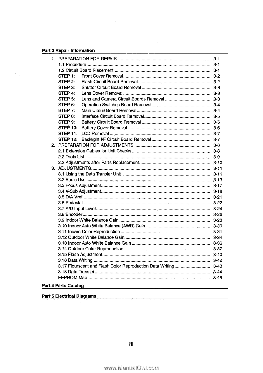
Part 3 Repair Information 1. PREPARATION FOR REPAIR 1.1 Procedure 1.2 Circuit Board Placement STEP 1: Front Cover Removal STEP 2: Flash Circuit Board Removal STEP 3: Shutter Circuit Board Removal STEP 4: Lens Cover Removal STEP 5: Lens and Camera Circuit Boards Removal STEP 6: Operation Switches Board Removal STEP 7: Main Circuit Board Removal STEP 8: Interface Circuit Board Removal STEP 9: Battery Circuit Board Removal STEP 10: Battery Cover Removal STEP 11: LCD Removal STEP 12: Backlight I/F Circuit Board Removal 2. PREPARATION FOR ADJUSTMENTS 2.1 Extension Cables for Unit Checks 2.2 Tools List 2.3 Adjustments after Parts Replacement 3. ADJUSTMENTS 3.1 Using the Data Transfer Unit 3.2 Basic Use 3.3 Focus Adjustment 3.4 V-Sub Adjustment 3.5 D/A Vref 3.6 Pedestal 3.7 A/D Input Level 3.8 Encoder 3.9 Indoor White Balance Gain 3.10 Indoor Auto White Balance (AWB) Gain 3.11 Indore Color Reproduction 3.12 Outdoor White Balance Gain 3.13 Indoor Auto White Balance Gain 3.14 Outdoor Color Reproduction 3.15 Flash Adjustment 3.16 Data Writing 3.17 Flourscent and Flash Color Reproduction Data Writing 3.18 Data Transfer EEPROM Map Part 4 Parts Catalog Part 5 Electrical Diagrams 3-1 3-1 3-1 3-2 3-2 3-3 3-3 3-3 3-4 3-4 3-5 3-5 3-6 3-7 3-7 3-8 3-8 3-9 3-10 3-11 3-11 3-13 3-17 3-18 3-21 3-22 3-24 3-26 3-28 3-30 3-31 3-34 3-36 3-37 3-40 3-42 3-43 3-44 3-45 III
-
 1
1 -
 2
2 -
 3
3 -
 4
4 -
 5
5 -
 6
6 -
 7
7 -
 8
8 -
 9
9 -
 10
10 -
 11
11 -
 12
12 -
13
-
14
-
15
-
16
-
17
-
18
-
19
-
20
-
21
-
22
-
23
-
24
-
25
-
26
-
27
-
28
-
29
-
30
-
31
-
32
-
33
-
34
-
35
-
36
-
37
-
38
-
39
-
40
-
41
-
42
-
43
-
44
-
45
-
46
-
47
-
48
-
49
-
50
-
51
-
52
-
53
-
54
-
55
-
56
-
57
-
58
-
59
-
60
-
61
-
62
-
63
-
64
-
65
-
66
-
67
-
68
-
69
-
70
-
71
-
72
-
73
-
74
-
75
-
76
-
77
-
78
-
79
-
80
-
81
-
82
-
83
-
84
-
85
-
86
-
87
-
88
-
89
-
90
-
91
-
92
-
93
-
94
-
95
-
96
-
97
-
98
-
99
-
100
-
101
-
102
-
103
-
104
-
105
-
106
-
107
-
108
-
109
-
110
-
111
-
112
-
113
-
114
-
115
-
116
-
117
-
118
-
119
-
120
-
121
-
122
-
123
-
124
-
125
-
126
-
127
-
128
-
129
-
130
-
131
-
132
-
133
-
134
-
135
-
136
-
137
-
138
-
139
 |
 |