Dell Optiplex-620 User Guide - Page 108
Before you begin any of the procedures in this follow the safety instructions in
 |
View all Dell Optiplex-620 manuals
Add to My Manuals
Save this manual to your list of manuals |
Page 108 highlights
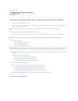
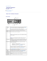
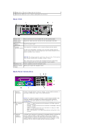
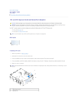
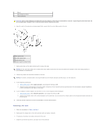
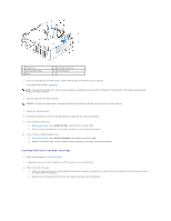
NOTE: Do not plug a telephone cable into the network connector. On computers with a network connector card, use the connector on the card. 4 network activity light 5 line-in connector It is recommended that you use Category 5 wiring and connectors for your network. If you must use Category 3 wiring, force the network speed to 10 Mbps to ensure reliable operation. Flashes a yellow light when the computer is transmitting or receiving network data. A high volume of network traffic may make this light appear to be in a steady "on" state. Use the blue line-in connector to attach a record/playback device such as a cassette player, CD player, or VCR. 6 line-out connector On computers with a sound card, use the connector on the card. Use the green line-out connector to attach headphones and most speakers with integrated amplifiers. 7 microphone connector On computers with a sound card, use the connector on the card. Use the pink microphone connector to attach a personal computer microphone for voice or musical input into a sound or telephony program. 8 USB 2.0 connectors (6) 9 video connector On computers with a sound card, the microphone connector is on the card. Use the back USB connectors for devices that typically remain connected, such as printers and keyboards. Plug the cable from your VGA-compatible monitor into the blue connector. NOTE: If you purchased an optional graphics card, this connector will be covered by a cap. Connect your monitor to the connector on the graphics card. Do not remove the cap. 10 serial connector NOTE: If you are using a graphics card that supports dual monitors, use the y-cable that came with your computer. Connect a serial device, such as a handheld device, to the serial port. The default designations are COM1 for serial connector 1 and COM2 for serial connector 2. For more information, see "System Setup Options." Inside Your Computer CAUTION: Before you begin any of the procedures in this section, follow the safety instructions in the Product Information Guide. CAUTION: To avoid electrical shock, always unplug your computer from the electrical outlet before removing the computer cover. NOTICE: Be careful when opening the computer cover to ensure that you do not accidentally disconnect cables from the system board. 1 drives bay (CD/DVD, floppy, and hard drive) 5 card slots 2 power supply 6 heat sink assembly 3 chassis intrusion switch 7 front I/O panel
-
 1
1 -
2
-
3
-
4
-
5
-
6
-
7
-
8
-
9
-
10
-
11
-
12
-
13
-
14
-
15
-
16
-
17
-
18
-
19
-
20
-
21
-
22
-
23
-
24
-
25
-
26
-
27
-
28
-
29
-
30
-
31
-
32
-
33
-
34
-
35
-
36
-
37
-
38
-
39
-
40
-
41
-
42
-
43
-
44
-
45
-
46
-
47
-
48
-
49
-
50
-
51
-
52
-
53
-
54
-
55
-
56
-
57
-
58
-
59
-
60
-
61
-
62
-
63
-
64
-
65
-
66
-
67
-
68
-
69
-
70
-
71
-
72
-
73
-
74
-
75
-
76
-
77
-
78
-
79
-
80
-
81
-
82
-
83
-
84
-
85
-
86
-
87
-
88
-
89
-
90
-
91
-
92
-
93
-
94
-
95
-
96
-
97
-
98
-
99
-
100
-
101
-
102
-
 103
103 -
 104
104 -
 105
105 -
 106
106 -
 107
107 -
 108
108 -
 109
109 -
 110
110 -
 111
111 -
 112
112 -
 113
113 -
114
-
115
-
116
-
117
-
118
-
119
-
120
-
121
-
122
-
123
-
124
-
125
-
126
-
127
-
128
-
129
-
130
-
131
-
132
-
133
-
134
-
135
-
136
-
137
-
138
-
139
-
140
-
141
-
142
-
143
-
144
-
145
-
146
-
147
-
148
-
149
-
150
-
151
-
152
-
153
-
154
-
155
-
156
-
157
-
158
-
159
-
160
-
161
-
162
-
163
-
164
-
165
-
166
-
167
-
168
-
169
-
170
-
171
-
172
-
173
-
174
-
175
-
176
-
177
-
178
-
179
-
180
-
181
-
182
-
183
-
184
-
185
-
186
-
187
-
188
-
189
-
190
-
191
-
192
-
193
-
194
-
195
-
196
-
197
-
198
-
199
-
200
-
201
-
202
-
203
-
204
-
205
-
206
-
207
-
208
-
209
-
210
-
211
-
212
-
213
-
214
-
215
-
216
-
217
-
218
-
219
-
220
-
221
 |
 |