Dell Optiplex-620 User Guide - Page 144
Key Combinations, Boot Sequence, Controls and Lights, Power - diagnostic lights 1 3 4
 |
View all Dell Optiplex-620 manuals
Add to My Manuals
Save this manual to your list of manuals |
Page 144 highlights
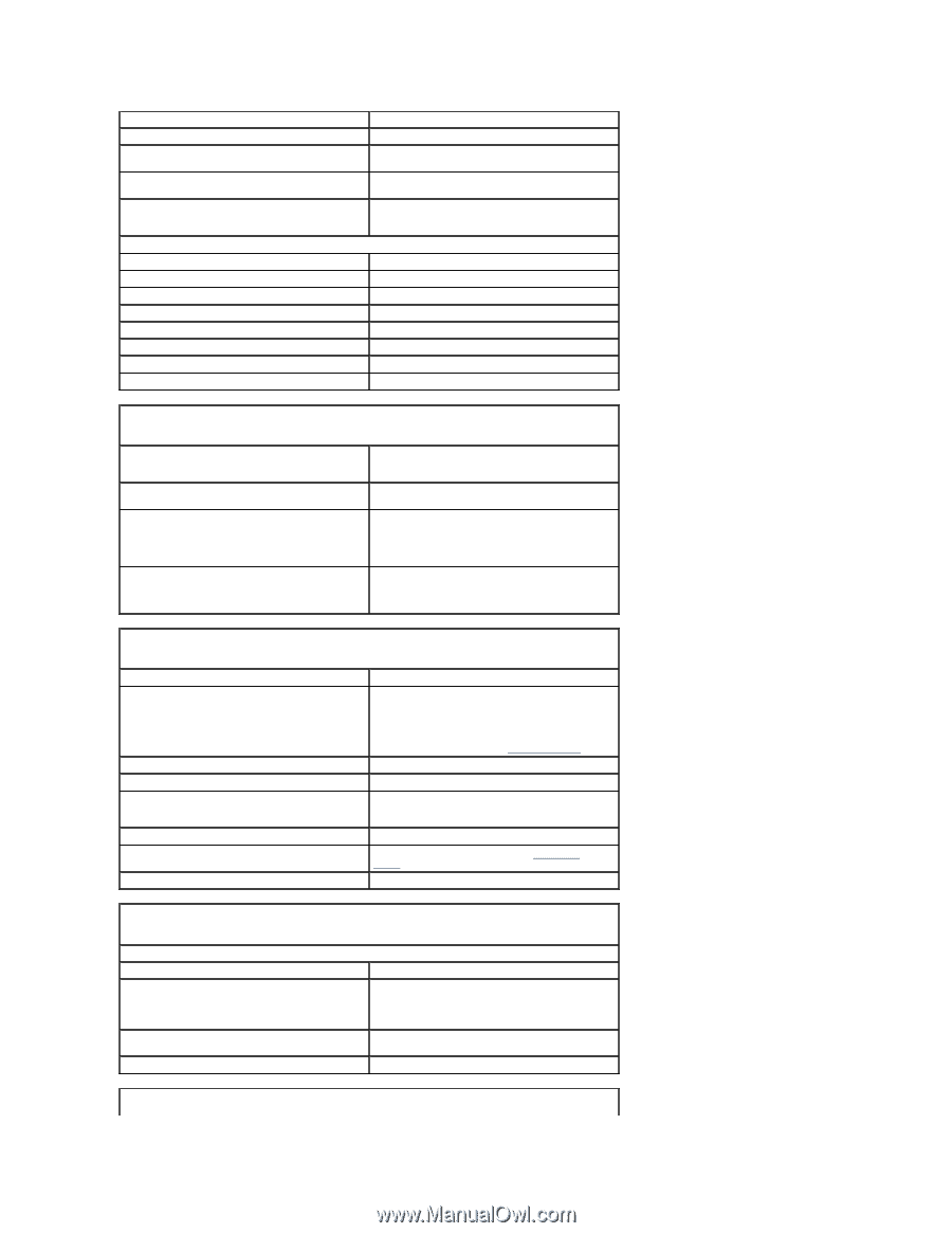
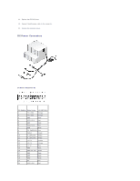
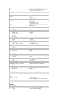
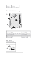
Video Network adapter Optional PS/2 with secondary serial port adapter USB Audio System board connectors: Primary IDE drive Serial ATA Floppy drive Serial Fan PCI 2.3 CD drive audio interface Front panel 15-hole VGA connector RJ45 connector two 6-pin mini-DINs two front-panel and six back-panel USB 2.0- compliant connectors three connectors for line-in, line-out, and microphone; two front-panel connectors for headphones and microphone 40-pin connector two 7-pin connectors 34-pin connector 12-pin connector for optional second serial port card 5-pin connector 120-pin connector 4-pin connector 40-pin connector Key Combinations or or in Microsoft® Windows® XP, brings up the Windows Security window; in MS-DOS® mode, restarts (reboots) the computer starts embedded system setup (during system startup only) automatically starts the computer from the network environment specified by the remote boot environment (PXE) rather than from one of the devices in the system setup Boot Sequence option (during system start-up only) displays a boot device menu that allows the user to enter a device for a single boot (during system startup only) as well as options to run hard-drive and system diagnostics Controls and Lights Power control Power light Hard-drive access light Link light Link integrity light (on integrated network adapter) Activity light (on integrated network adapter) Diagnostic lights Standby power light push button green light - Blinking green indicates a sleep mode; solid green indicates a power-on state. amber light - Blinking amber indicates a problem with an installed device; solid amber indicates an internal power problem (see "Power Problems"). green solid green light indicates network connection green light for 10-Mb operation; orange light for 100Mb operation; yellow light for a 1000-Mb (1-Gb) operation yellow blinking light Four lights on the back panel. See "Diagnostic Lights." AUX_PWR on the system board Power DC power supply: Wattage Heat dissipation Voltage Backup battery 280 W 956 BTU/hr NOTE: Heat dissipation is calculated based upon the power supply wattage rating. manual selection power supplies - 90 to 135 V at 50/60 Hz; 180 to 265 V at 50/60 Hz 3-V CR2032 lithium coin cell
-
 1
1 -
2
-
3
-
4
-
5
-
6
-
7
-
8
-
9
-
10
-
11
-
12
-
13
-
14
-
15
-
16
-
17
-
18
-
19
-
20
-
21
-
22
-
23
-
24
-
25
-
26
-
27
-
28
-
29
-
30
-
31
-
32
-
33
-
34
-
35
-
36
-
37
-
38
-
39
-
40
-
41
-
42
-
43
-
44
-
45
-
46
-
47
-
48
-
49
-
50
-
51
-
52
-
53
-
54
-
55
-
56
-
57
-
58
-
59
-
60
-
61
-
62
-
63
-
64
-
65
-
66
-
67
-
68
-
69
-
70
-
71
-
72
-
73
-
74
-
75
-
76
-
77
-
78
-
79
-
80
-
81
-
82
-
83
-
84
-
85
-
86
-
87
-
88
-
89
-
90
-
91
-
92
-
93
-
94
-
95
-
96
-
97
-
98
-
99
-
100
-
101
-
102
-
103
-
104
-
105
-
106
-
107
-
108
-
109
-
110
-
111
-
112
-
113
-
114
-
115
-
116
-
117
-
118
-
119
-
120
-
121
-
122
-
123
-
124
-
125
-
126
-
127
-
128
-
129
-
130
-
131
-
132
-
133
-
134
-
135
-
136
-
137
-
138
-
 139
139 -
 140
140 -
 141
141 -
 142
142 -
 143
143 -
 144
144 -
 145
145 -
 146
146 -
 147
147 -
 148
148 -
 149
149 -
150
-
151
-
152
-
153
-
154
-
155
-
156
-
157
-
158
-
159
-
160
-
161
-
162
-
163
-
164
-
165
-
166
-
167
-
168
-
169
-
170
-
171
-
172
-
173
-
174
-
175
-
176
-
177
-
178
-
179
-
180
-
181
-
182
-
183
-
184
-
185
-
186
-
187
-
188
-
189
-
190
-
191
-
192
-
193
-
194
-
195
-
196
-
197
-
198
-
199
-
200
-
201
-
202
-
203
-
204
-
205
-
206
-
207
-
208
-
209
-
210
-
211
-
212
-
213
-
214
-
215
-
216
-
217
-
218
-
219
-
220
-
221
 |
 |