Dell Optiplex-620 User Guide - Page 125
Power Cable Connectors, Connecting and Disconnecting Drive Cables, Removing a CD/DVD Drive
 |
View all Dell Optiplex-620 manuals
Add to My Manuals
Save this manual to your list of manuals |
Page 125 highlights
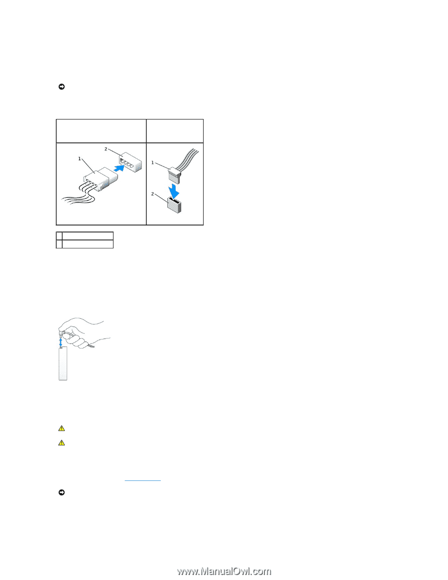
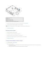
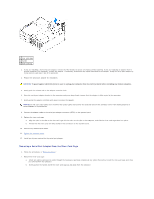
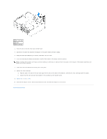
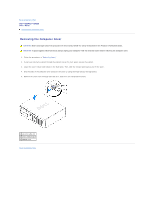
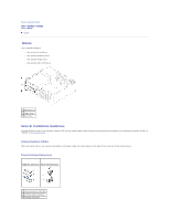
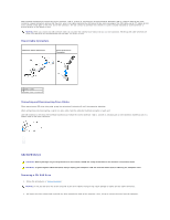
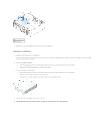
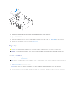
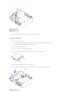
Most interface connectors are keyed for correct insertion; that is, a notch or a missing pin on one connector matches a tab or a filled-in hole on the other connector. Keyed connectors ensure that the pin-1 wire in the cable (indicated by the colored stripe along one edge of the IDE cable-serial ATA cables do not use a colored stripe) goes to the pin-1 end of the connector. The pin-1 end of a connector on a board or a card is usually indicated by a silk-screened "1" printed directly on the board or card. NOTICE: When you connect an IDE interface cable, do not place the colored stripe away from pin 1 of the connector. Reversing the cable prevents the drive from operating and could damage the controller, the drive, or both. Power Cable Connectors IDE Drive Power Connector Serial ATA Power Connector 1 power cable 2 power input connector Connecting and Disconnecting Drive Cables When removing an IDE drive data cable, grasp the colored pull-tab and pull until the connector detaches. When connecting and disconnecting a serial ATA data cable, hold the cable by the black connector at each end. Like IDE connectors, the serial ATA interface connectors are keyed for correct insertion; that is, a notch or a missing pin on one connector matches a tab or a filled-in hole on the other connector. CD/DVD Drive CAUTION: Before you begin any of the procedures in this section, follow the safety instructions in the Product Information Guide. CAUTION: To guard against electrical shock, always unplug your computer from the electrical outlet before removing the computer cover. Removing a CD/DVD Drive 1. Follow the procedures in "Before You Begin." NOTICE: Do not pull the drive out of the computer by the drive cables. Doing so may cause damage to cables and the cable connectors. 2. Pull up on the drive release latch and slide the drive towards the back of the computer. Then, lift up to remove the drive from the computer.
-
 1
1 -
2
-
3
-
4
-
5
-
6
-
7
-
8
-
9
-
10
-
11
-
12
-
13
-
14
-
15
-
16
-
17
-
18
-
19
-
20
-
21
-
22
-
23
-
24
-
25
-
26
-
27
-
28
-
29
-
30
-
31
-
32
-
33
-
34
-
35
-
36
-
37
-
38
-
39
-
40
-
41
-
42
-
43
-
44
-
45
-
46
-
47
-
48
-
49
-
50
-
51
-
52
-
53
-
54
-
55
-
56
-
57
-
58
-
59
-
60
-
61
-
62
-
63
-
64
-
65
-
66
-
67
-
68
-
69
-
70
-
71
-
72
-
73
-
74
-
75
-
76
-
77
-
78
-
79
-
80
-
81
-
82
-
83
-
84
-
85
-
86
-
87
-
88
-
89
-
90
-
91
-
92
-
93
-
94
-
95
-
96
-
97
-
98
-
99
-
100
-
101
-
102
-
103
-
104
-
105
-
106
-
107
-
108
-
109
-
110
-
111
-
112
-
113
-
114
-
115
-
116
-
117
-
118
-
119
-
 120
120 -
 121
121 -
 122
122 -
 123
123 -
 124
124 -
 125
125 -
 126
126 -
 127
127 -
 128
128 -
 129
129 -
 130
130 -
131
-
132
-
133
-
134
-
135
-
136
-
137
-
138
-
139
-
140
-
141
-
142
-
143
-
144
-
145
-
146
-
147
-
148
-
149
-
150
-
151
-
152
-
153
-
154
-
155
-
156
-
157
-
158
-
159
-
160
-
161
-
162
-
163
-
164
-
165
-
166
-
167
-
168
-
169
-
170
-
171
-
172
-
173
-
174
-
175
-
176
-
177
-
178
-
179
-
180
-
181
-
182
-
183
-
184
-
185
-
186
-
187
-
188
-
189
-
190
-
191
-
192
-
193
-
194
-
195
-
196
-
197
-
198
-
199
-
200
-
201
-
202
-
203
-
204
-
205
-
206
-
207
-
208
-
209
-
210
-
211
-
212
-
213
-
214
-
215
-
216
-
217
-
218
-
219
-
220
-
221
 |
 |