Dell PowerEdge C6105 Hardware Owner's Manual - Page 111
See Replace the cooling fans. See Installing a Cooling Fan
 |
View all Dell PowerEdge C6105 manuals
Add to My Manuals
Save this manual to your list of manuals |
Page 111 highlights
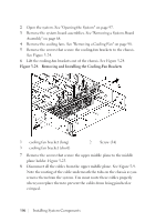
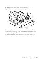
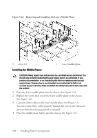
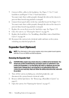
5 Replace the screws that secure the middle plane holder to the chassis. See Figure 3-27. 6 Place the mid-plane holder support into the chassis. See Figure 3-26. 7 Replace the screws that secure the mid-plane holder support to the chassis. See Figure 3-26. 8 Place the upper middle plane on the middle plane holder. See Figure 3- 25. 9 Replace the screws that secure the middle plane to the middle plane holder. Figure 3-25. 10 Connect all the cables to the upper middle plane. See Figure 5-9. You must route these cables properly through the tabs on the chassis to prevent them from being pinched or crimped. 11 Place the fan bracket into the chassis. Figure 3-24. 12 Replace the screws that secure the fan bracket to the chassis. Figure 324. 13 Replace the cooling fans. See "Installing a Cooling Fan" on page 100. 14 Replace the system-board assemblies. See "Installing a System-Board Assembly" on page 69. 15 Close the system, see "Closing the System" on page 98. 16 Reconnect the system to its electrical outlet and turn on the system, including any attached peripherals. Installing System Components | 111
-
 1
1 -
2
-
3
-
4
-
5
-
6
-
7
-
8
-
9
-
10
-
11
-
12
-
13
-
14
-
15
-
16
-
17
-
18
-
19
-
20
-
21
-
22
-
23
-
24
-
25
-
26
-
27
-
28
-
29
-
30
-
31
-
32
-
33
-
34
-
35
-
36
-
37
-
38
-
39
-
40
-
41
-
42
-
43
-
44
-
45
-
46
-
47
-
48
-
49
-
50
-
51
-
52
-
53
-
54
-
55
-
56
-
57
-
58
-
59
-
60
-
61
-
62
-
63
-
64
-
65
-
66
-
67
-
68
-
69
-
70
-
71
-
72
-
73
-
74
-
75
-
76
-
77
-
78
-
79
-
80
-
81
-
82
-
83
-
84
-
85
-
86
-
87
-
88
-
89
-
90
-
91
-
92
-
93
-
94
-
95
-
96
-
97
-
98
-
99
-
100
-
101
-
102
-
103
-
104
-
105
-
 106
106 -
 107
107 -
 108
108 -
 109
109 -
 110
110 -
 111
111 -
 112
112 -
 113
113 -
 114
114 -
 115
115 -
 116
116 -
117
-
118
-
119
-
120
-
121
-
122
-
123
-
124
-
125
-
126
-
127
-
128
-
129
-
130
-
131
-
132
-
133
-
134
-
135
-
136
-
137
-
138
-
139
-
140
-
141
-
142
-
143
-
144
-
145
-
146
-
147
-
148
-
149
-
150
-
151
-
152
-
153
-
154
-
155
-
156
-
157
-
158
-
159
-
160
-
161
-
162
-
163
-
164
-
165
-
166
 |
 |