Dell PowerEdge C6105 Hardware Owner's Manual - Page 122
See Disconnect front panel cables from the fan controller board. See
 |
View all Dell PowerEdge C6105 manuals
Add to My Manuals
Save this manual to your list of manuals |
Page 122 highlights
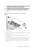
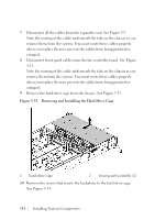
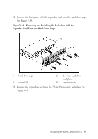
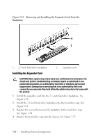
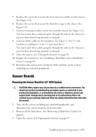
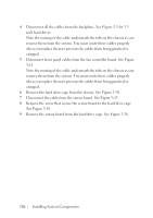
2 Remove all the hard drives. See "Removing a Hard-Drive Carrier" on page 61. 3 Open the system. See "Opening the System" on page 97. 4 Disconnect all the cables from the backplane. See Figure 5-3 for 3.5- inch hard drives and Figure 5-6 for 2.5-inch hard drives. Note the routing of the cable underneath the tabs on the chassis as you remove them from the system. You must route these cables properly when you replace them to prevent the cables from being pinched or crimped. 5 Disconnect front panel cables from the fan controller board. See Figure 5-11. Note the routing of the cable underneath the tabs on the chassis as you remove them from the system. You must route these cables properly when you replace them to prevent the cables from being pinched or crimped. 6 Remove the screws that secure the hard-drive cage to the chassis. See Figure 3-29. 7 Remove the screws that secure the front-panel assemblies to the chassis. See Figure 3-30. 8 Remove the hard-drive cage from the chassis. See Figure 3-30. 9 Remove the screws that secure the front-panel assembly to the harddrive cage. See Figure 3-36. 10 Remove the front-panel assembly from the hard-drive cage. See Figure 3-36. 122 | Installing System Components
-
 1
1 -
2
-
3
-
4
-
5
-
6
-
7
-
8
-
9
-
10
-
11
-
12
-
13
-
14
-
15
-
16
-
17
-
18
-
19
-
20
-
21
-
22
-
23
-
24
-
25
-
26
-
27
-
28
-
29
-
30
-
31
-
32
-
33
-
34
-
35
-
36
-
37
-
38
-
39
-
40
-
41
-
42
-
43
-
44
-
45
-
46
-
47
-
48
-
49
-
50
-
51
-
52
-
53
-
54
-
55
-
56
-
57
-
58
-
59
-
60
-
61
-
62
-
63
-
64
-
65
-
66
-
67
-
68
-
69
-
70
-
71
-
72
-
73
-
74
-
75
-
76
-
77
-
78
-
79
-
80
-
81
-
82
-
83
-
84
-
85
-
86
-
87
-
88
-
89
-
90
-
91
-
92
-
93
-
94
-
95
-
96
-
97
-
98
-
99
-
100
-
101
-
102
-
103
-
104
-
105
-
106
-
107
-
108
-
109
-
110
-
111
-
112
-
113
-
114
-
115
-
116
-
 117
117 -
 118
118 -
 119
119 -
 120
120 -
 121
121 -
 122
122 -
 123
123 -
 124
124 -
 125
125 -
 126
126 -
 127
127 -
128
-
129
-
130
-
131
-
132
-
133
-
134
-
135
-
136
-
137
-
138
-
139
-
140
-
141
-
142
-
143
-
144
-
145
-
146
-
147
-
148
-
149
-
150
-
151
-
152
-
153
-
154
-
155
-
156
-
157
-
158
-
159
-
160
-
161
-
162
-
163
-
164
-
165
-
166
 |
 |