Dell PowerEdge C6105 Hardware Owner's Manual - Page 82
System Memory, Supported DIMM Configuration
 |
View all Dell PowerEdge C6105 manuals
Add to My Manuals
Save this manual to your list of manuals |
Page 82 highlights
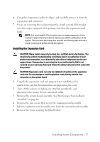
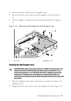
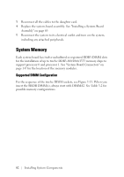
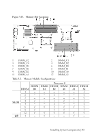
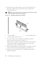
3 Reconnect all the cables to the daughter card. 4 Replace the system-board assembly. See "Installing a System-Board Assembly" on page 69. 5 Reconnect the system to its electrical outlet and turn on the system, including any attached peripherals. System Memory Each system board has twelve unbuffered or registered DDR3-DIMM slots for the installation of up to twelve DDR3-800/1066/1333 memory chips to support processor 0 and processor 1. See "System Board Connectors" on page 147 for the location of the memory modules. Supported DIMM Configuration For the sequence of the twelve DIMM sockets, see Figure 3-13. When you insert the SR/DR DIMM(s), always start with DIMMA2. See Table 3-2 for possible memory configurations. 82 | Installing System Components
-
 1
1 -
2
-
3
-
4
-
5
-
6
-
7
-
8
-
9
-
10
-
11
-
12
-
13
-
14
-
15
-
16
-
17
-
18
-
19
-
20
-
21
-
22
-
23
-
24
-
25
-
26
-
27
-
28
-
29
-
30
-
31
-
32
-
33
-
34
-
35
-
36
-
37
-
38
-
39
-
40
-
41
-
42
-
43
-
44
-
45
-
46
-
47
-
48
-
49
-
50
-
51
-
52
-
53
-
54
-
55
-
56
-
57
-
58
-
59
-
60
-
61
-
62
-
63
-
64
-
65
-
66
-
67
-
68
-
69
-
70
-
71
-
72
-
73
-
74
-
75
-
76
-
 77
77 -
 78
78 -
 79
79 -
 80
80 -
 81
81 -
 82
82 -
 83
83 -
 84
84 -
 85
85 -
 86
86 -
 87
87 -
88
-
89
-
90
-
91
-
92
-
93
-
94
-
95
-
96
-
97
-
98
-
99
-
100
-
101
-
102
-
103
-
104
-
105
-
106
-
107
-
108
-
109
-
110
-
111
-
112
-
113
-
114
-
115
-
116
-
117
-
118
-
119
-
120
-
121
-
122
-
123
-
124
-
125
-
126
-
127
-
128
-
129
-
130
-
131
-
132
-
133
-
134
-
135
-
136
-
137
-
138
-
139
-
140
-
141
-
142
-
143
-
144
-
145
-
146
-
147
-
148
-
149
-
150
-
151
-
152
-
153
-
154
-
155
-
156
-
157
-
158
-
159
-
160
-
161
-
162
-
163
-
164
-
165
-
166
 |
 |