Dell PowerEdge R540 EMC Installation and Service Manual - Page 104
Removing the non-fabric processor from the processor and heat sink module
 |
View all Dell PowerEdge R540 manuals
Add to My Manuals
Save this manual to your list of manuals |
Page 104 highlights
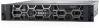
Figure 58. Removing processor and heat sink module Next steps Installing a processor and heat sink module on page 108 Removing the non-fabric processor from the processor and heat sink module Prerequisites NOTE: Only remove the processor from the processor and heat sink module if you are replacing the processor or heat sink. This procedure is not required when replacing a system board. 1. Follow the safety guidelines listed in Safety instructions on page 66. 2. Follow the procedure listed in Before working inside your system on page 67. 3. Removing the air shroud on page 75 4. Removing a processor and heat sink module on page 103 Steps 1. Place the heat sink with the processor side facing up. 2. Insert a flat blade screwdriver into the release slot marked with a yellow label. Twist (do not pry) the screwdriver to break the thermal paste seal. 3. Push the retaining clips on the processor bracket to unlock the bracket from the heat sink. 104 Installing and removing system components
-
 1
1 -
2
-
3
-
4
-
5
-
6
-
7
-
8
-
9
-
10
-
11
-
12
-
13
-
14
-
15
-
16
-
17
-
18
-
19
-
20
-
21
-
22
-
23
-
24
-
25
-
26
-
27
-
28
-
29
-
30
-
31
-
32
-
33
-
34
-
35
-
36
-
37
-
38
-
39
-
40
-
41
-
42
-
43
-
44
-
45
-
46
-
47
-
48
-
49
-
50
-
51
-
52
-
53
-
54
-
55
-
56
-
57
-
58
-
59
-
60
-
61
-
62
-
63
-
64
-
65
-
66
-
67
-
68
-
69
-
70
-
71
-
72
-
73
-
74
-
75
-
76
-
77
-
78
-
79
-
80
-
81
-
82
-
83
-
84
-
85
-
86
-
87
-
88
-
89
-
90
-
91
-
92
-
93
-
94
-
95
-
96
-
97
-
98
-
 99
99 -
 100
100 -
 101
101 -
 102
102 -
 103
103 -
 104
104 -
 105
105 -
 106
106 -
 107
107 -
 108
108 -
 109
109 -
110
-
111
-
112
-
113
-
114
-
115
-
116
-
117
-
118
-
119
-
120
-
121
-
122
-
123
-
124
-
125
-
126
-
127
-
128
-
129
-
130
-
131
-
132
-
133
-
134
-
135
-
136
-
137
-
138
-
139
-
140
-
141
-
142
-
143
-
144
-
145
-
146
-
147
-
148
-
149
-
150
-
151
-
152
-
153
-
154
-
155
-
156
-
157
-
158
-
159
-
160
-
161
-
162
-
163
-
164
-
165
-
166
-
167
-
168
-
169
-
170
-
171
-
172
-
173
-
174
-
175
 |
 |
