Dell PowerEdge R540 EMC Installation and Service Manual - Page 77
Installing the air shroud
 |
View all Dell PowerEdge R540 manuals
Add to My Manuals
Save this manual to your list of manuals |
Page 77 highlights
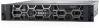
Next steps 1. If applicable, Installing the air shroud on page 77 2. Follow the procedure listed in After working inside your system on page 67. Installing the air shroud Prerequisites 1. Follow the safety guidelines listed in Safety instructions on page 66. 2. Follow the procedure listed in Before working inside your system on page 67. 3. If applicable, route the cables inside the system along the system wall and secure the cables by using the cable latch. Steps 1. Align the tabs on the air shroud with the slots on the system. 2. Lower the air shroud into the system until it is firmly seated. When firmly seated, the memory socket numbers marked on the air shroud align with the respective memory sockets. Figure 32. Installing air shroud NOTE: The procedure to install the air shroud for 2 x 3.5-inch rear drive system is identical. Installing and removing system components 77
-
 1
1 -
2
-
3
-
4
-
5
-
6
-
7
-
8
-
9
-
10
-
11
-
12
-
13
-
14
-
15
-
16
-
17
-
18
-
19
-
20
-
21
-
22
-
23
-
24
-
25
-
26
-
27
-
28
-
29
-
30
-
31
-
32
-
33
-
34
-
35
-
36
-
37
-
38
-
39
-
40
-
41
-
42
-
43
-
44
-
45
-
46
-
47
-
48
-
49
-
50
-
51
-
52
-
53
-
54
-
55
-
56
-
57
-
58
-
59
-
60
-
61
-
62
-
63
-
64
-
65
-
66
-
67
-
68
-
69
-
70
-
71
-
 72
72 -
 73
73 -
 74
74 -
 75
75 -
 76
76 -
 77
77 -
 78
78 -
 79
79 -
 80
80 -
 81
81 -
 82
82 -
83
-
84
-
85
-
86
-
87
-
88
-
89
-
90
-
91
-
92
-
93
-
94
-
95
-
96
-
97
-
98
-
99
-
100
-
101
-
102
-
103
-
104
-
105
-
106
-
107
-
108
-
109
-
110
-
111
-
112
-
113
-
114
-
115
-
116
-
117
-
118
-
119
-
120
-
121
-
122
-
123
-
124
-
125
-
126
-
127
-
128
-
129
-
130
-
131
-
132
-
133
-
134
-
135
-
136
-
137
-
138
-
139
-
140
-
141
-
142
-
143
-
144
-
145
-
146
-
147
-
148
-
149
-
150
-
151
-
152
-
153
-
154
-
155
-
156
-
157
-
158
-
159
-
160
-
161
-
162
-
163
-
164
-
165
-
166
-
167
-
168
-
169
-
170
-
171
-
172
-
173
-
174
-
175
 |
 |
