Dell PowerEdge R540 EMC Installation and Service Manual - Page 18
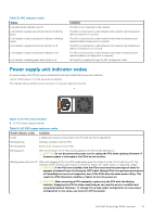
Table 11. Back panel features of R540, Features, Description
 |
View all Dell PowerEdge R540 manuals
Add to My Manuals
Save this manual to your list of manuals |
Page 18 highlights
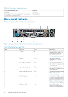
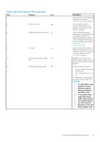
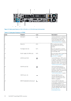
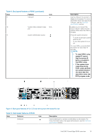
Figure 10. Back panel features of 12 x 3.5-inch + 2 x 3.5-inch (rear) drive system Table 11. Back panel features of R540 Item Features Icon 1 Serial port 2 Drive (2) N/A 3 Full height riser slot N/A 4 Power supply unit (PSU) (2) N/A 5 LOM riser port (2) 6 Ethernet port (2) 7 USB 3.0 port (2) 8 iDRAC9 dedicated network port 18 Dell EMC PowerEdge R540 overview Description Use the serial port to connect a serial device to the system. For more information about the supported serial port, see the Technical specifications section. Two optional rear drives supported for 12 x 3.5 inch system. Use the card slots to connect full-height PCIe expansion cards on full height riser. For information about supported PSUs, see the Technical specifications section. Use the Ethernet or SFP+ ports to connect Local Area Networks (LANs) to the system. For more information about the supported Ethernet or SFP+ ports, see the Technical specifications section. Use the Ethernet ports to connect Local Area Networks (LANs) to the system. For more information about the supported Ethernet ports, see the Technical specifications section. Use the USB 3.0 port to connect USB devices to the system. These ports are 4-pin, USB 3.0-compliant. Use the iDRAC9 dedicated network port to securely access the embedded iDRAC on a separate management network, see the Integrated Dell Remote Access Controller User's Guide at www.dell.com/ poweredgemanuals.
-
 1
1 -
2
-
3
-
4
-
5
-
6
-
7
-
8
-
9
-
10
-
11
-
12
-
 13
13 -
 14
14 -
 15
15 -
 16
16 -
 17
17 -
 18
18 -
 19
19 -
 20
20 -
 21
21 -
 22
22 -
 23
23 -
24
-
25
-
26
-
27
-
28
-
29
-
30
-
31
-
32
-
33
-
34
-
35
-
36
-
37
-
38
-
39
-
40
-
41
-
42
-
43
-
44
-
45
-
46
-
47
-
48
-
49
-
50
-
51
-
52
-
53
-
54
-
55
-
56
-
57
-
58
-
59
-
60
-
61
-
62
-
63
-
64
-
65
-
66
-
67
-
68
-
69
-
70
-
71
-
72
-
73
-
74
-
75
-
76
-
77
-
78
-
79
-
80
-
81
-
82
-
83
-
84
-
85
-
86
-
87
-
88
-
89
-
90
-
91
-
92
-
93
-
94
-
95
-
96
-
97
-
98
-
99
-
100
-
101
-
102
-
103
-
104
-
105
-
106
-
107
-
108
-
109
-
110
-
111
-
112
-
113
-
114
-
115
-
116
-
117
-
118
-
119
-
120
-
121
-
122
-
123
-
124
-
125
-
126
-
127
-
128
-
129
-
130
-
131
-
132
-
133
-
134
-
135
-
136
-
137
-
138
-
139
-
140
-
141
-
142
-
143
-
144
-
145
-
146
-
147
-
148
-
149
-
150
-
151
-
152
-
153
-
154
-
155
-
156
-
157
-
158
-
159
-
160
-
161
-
162
-
163
-
164
-
165
-
166
-
167
-
168
-
169
-
170
-
171
-
172
-
173
-
174
-
175
 |
 |
