Dell PowerEdge R540 EMC Installation and Service Manual - Page 145
Rear drive cage, Removing the rear drive cage
 |
View all Dell PowerEdge R540 manuals
Add to My Manuals
Save this manual to your list of manuals |
Page 145 highlights
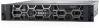
Figure 109. Cable routing - 2 x 3.5-inch Hybrid backplane with NVMe U.2 SSD 1. drive backplane 3. backplane power cable 5. SATA cable (BP:BP_C0 to MB SATA_C1) 7. Power interposer board (PIB) 9. PCIe cable (BP:BP PCIe A0 to MB PCIe_A0) 2. backplane signal cable (BP:BP_SIG1 to MB:BP_SIG1) 4. SATA cable (BP:BP_B0 to MB SATA_B1) 6. SATA cable (BP:BP_A0 to MB SATA_A1) 8. PCIe cable (BP:BP PCIe B0 to MB Interposer_A) Rear drive cage Removing the rear drive cage Prerequisites 1. Follow the safety guidelines listed in Safety instructions on page 66. 2. Follow the procedure listed in Before working inside your system on page 67. 3. Remove all the drives. 4. Disconnect all the cables from the rear drive backplane. Steps 1. Using Phillips #2 screwdriver, loosen the screws that secure the drive cage to the system. 2. Pull and hold the screws to lift the drive cage away from the system. Installing and removing system components 145
-
 1
1 -
2
-
3
-
4
-
5
-
6
-
7
-
8
-
9
-
10
-
11
-
12
-
13
-
14
-
15
-
16
-
17
-
18
-
19
-
20
-
21
-
22
-
23
-
24
-
25
-
26
-
27
-
28
-
29
-
30
-
31
-
32
-
33
-
34
-
35
-
36
-
37
-
38
-
39
-
40
-
41
-
42
-
43
-
44
-
45
-
46
-
47
-
48
-
49
-
50
-
51
-
52
-
53
-
54
-
55
-
56
-
57
-
58
-
59
-
60
-
61
-
62
-
63
-
64
-
65
-
66
-
67
-
68
-
69
-
70
-
71
-
72
-
73
-
74
-
75
-
76
-
77
-
78
-
79
-
80
-
81
-
82
-
83
-
84
-
85
-
86
-
87
-
88
-
89
-
90
-
91
-
92
-
93
-
94
-
95
-
96
-
97
-
98
-
99
-
100
-
101
-
102
-
103
-
104
-
105
-
106
-
107
-
108
-
109
-
110
-
111
-
112
-
113
-
114
-
115
-
116
-
117
-
118
-
119
-
120
-
121
-
122
-
123
-
124
-
125
-
126
-
127
-
128
-
129
-
130
-
131
-
132
-
133
-
134
-
135
-
136
-
137
-
138
-
139
-
 140
140 -
 141
141 -
 142
142 -
 143
143 -
 144
144 -
 145
145 -
 146
146 -
 147
147 -
 148
148 -
 149
149 -
 150
150 -
151
-
152
-
153
-
154
-
155
-
156
-
157
-
158
-
159
-
160
-
161
-
162
-
163
-
164
-
165
-
166
-
167
-
168
-
169
-
170
-
171
-
172
-
173
-
174
-
175
 |
 |
