Dell PowerEdge R540 EMC Installation and Service Manual - Page 75
Air shroud, Removing the air shroud
 |
View all Dell PowerEdge R540 manuals
Add to My Manuals
Save this manual to your list of manuals |
Page 75 highlights
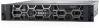
Figure 30. Inside the system with rear drive cage 1. Information tag 3. Cooling fans 5. CPU 1 7. System board 9. Internal PERC riser 11. Butterfly riser 13. Low profile riser right 15. Drive cage (rear) Air shroud 2. Drive backplane 4. Memory module 6. CPU 2 8. LOM riser card 10. Air shroud 12. Air shroud (12 x 3.5 inch + 2 x 3.5 inch rear hard drive system) 14. Low profile riser left Removing the air shroud Prerequisites CAUTION: Never operate your system with the air shroud removed. The system may get overheated quickly, resulting in shutdown of the system and loss of data. 1. Follow the safety guidelines listed in Safety instructions on page 66. 2. Follow the procedure listed in Before working inside your system on page 67. 3. If installed, remove the butterfly riser. Steps Hold the air shroud at both ends and lift it away from the system. Installing and removing system components 75
-
 1
1 -
2
-
3
-
4
-
5
-
6
-
7
-
8
-
9
-
10
-
11
-
12
-
13
-
14
-
15
-
16
-
17
-
18
-
19
-
20
-
21
-
22
-
23
-
24
-
25
-
26
-
27
-
28
-
29
-
30
-
31
-
32
-
33
-
34
-
35
-
36
-
37
-
38
-
39
-
40
-
41
-
42
-
43
-
44
-
45
-
46
-
47
-
48
-
49
-
50
-
51
-
52
-
53
-
54
-
55
-
56
-
57
-
58
-
59
-
60
-
61
-
62
-
63
-
64
-
65
-
66
-
67
-
68
-
69
-
 70
70 -
 71
71 -
 72
72 -
 73
73 -
 74
74 -
 75
75 -
 76
76 -
 77
77 -
 78
78 -
 79
79 -
 80
80 -
81
-
82
-
83
-
84
-
85
-
86
-
87
-
88
-
89
-
90
-
91
-
92
-
93
-
94
-
95
-
96
-
97
-
98
-
99
-
100
-
101
-
102
-
103
-
104
-
105
-
106
-
107
-
108
-
109
-
110
-
111
-
112
-
113
-
114
-
115
-
116
-
117
-
118
-
119
-
120
-
121
-
122
-
123
-
124
-
125
-
126
-
127
-
128
-
129
-
130
-
131
-
132
-
133
-
134
-
135
-
136
-
137
-
138
-
139
-
140
-
141
-
142
-
143
-
144
-
145
-
146
-
147
-
148
-
149
-
150
-
151
-
152
-
153
-
154
-
155
-
156
-
157
-
158
-
159
-
160
-
161
-
162
-
163
-
164
-
165
-
166
-
167
-
168
-
169
-
170
-
171
-
172
-
173
-
174
-
175
 |
 |
