Dell PowerEdge R640 EMC PowerEdge R640 Installation and Service Manual - Page 103
Removing the processor from the processor and heat sink module
 |
View all Dell PowerEdge R640 manuals
Add to My Manuals
Save this manual to your list of manuals |
Page 103 highlights
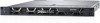
a. Loosen the first screw three turns. b. Loosen the second screw completely. c. Return to the first screw and loosen it completely. 2. Pushing both blue retention clips simultaneously, lift the processor and heat sink module (PHM) processor and heat sink module 3. Set the PHM aside with the processor side facing up. Figure 44. Removing the processor and heat sink module Next steps Install the PHM. Removing the processor from the processor and heat sink module Prerequisites NOTE: Only remove the processor from the processor and heat sink module if you are replacing the processor or heat sink. This procedure is not required when replacing a system board. 1. Follow the safety guidelines listed in Safety instructions on page 71. 2. Follow the procedure listed in Before working inside your system on page 72. 3. Remove the air shroud. 4. Remove the processor and heat sink module. Steps 1. Place the heat sink with the processor side facing up. 2. Insert a flat blade screwdriver into the release slot marked with a yellow label. Twist (do not pry) the screwdriver to break the thermal paste seal. 3. Push the retaining clips on the processor bracket to unlock the bracket from the heat sink. Installing and removing system components 103
-
 1
1 -
2
-
3
-
4
-
5
-
6
-
7
-
8
-
9
-
10
-
11
-
12
-
13
-
14
-
15
-
16
-
17
-
18
-
19
-
20
-
21
-
22
-
23
-
24
-
25
-
26
-
27
-
28
-
29
-
30
-
31
-
32
-
33
-
34
-
35
-
36
-
37
-
38
-
39
-
40
-
41
-
42
-
43
-
44
-
45
-
46
-
47
-
48
-
49
-
50
-
51
-
52
-
53
-
54
-
55
-
56
-
57
-
58
-
59
-
60
-
61
-
62
-
63
-
64
-
65
-
66
-
67
-
68
-
69
-
70
-
71
-
72
-
73
-
74
-
75
-
76
-
77
-
78
-
79
-
80
-
81
-
82
-
83
-
84
-
85
-
86
-
87
-
88
-
89
-
90
-
91
-
92
-
93
-
94
-
95
-
96
-
97
-
 98
98 -
 99
99 -
 100
100 -
 101
101 -
 102
102 -
 103
103 -
 104
104 -
 105
105 -
 106
106 -
 107
107 -
 108
108 -
109
-
110
-
111
-
112
-
113
-
114
-
115
-
116
-
117
-
118
-
119
-
120
-
121
-
122
-
123
-
124
-
125
-
126
-
127
-
128
-
129
-
130
-
131
-
132
-
133
-
134
-
135
-
136
-
137
-
138
-
139
-
140
-
141
-
142
-
143
-
144
-
145
-
146
-
147
-
148
-
149
-
150
-
151
-
152
-
153
-
154
-
155
-
156
-
157
-
158
-
159
-
160
-
161
-
162
-
163
-
164
-
165
-
166
-
167
-
168
-
169
-
170
-
171
-
172
-
173
 |
 |
