Dell PowerEdge R640 EMC PowerEdge R640 Installation and Service Manual - Page 134
Removing the backplane cover, Installing the backplane
 |
View all Dell PowerEdge R640 manuals
Add to My Manuals
Save this manual to your list of manuals |
Page 134 highlights
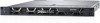
5. NVMe cable connector 7. NVMe cable connector 9. backplane to expander board cable connector 6. power cable connector 8. backplane to expander board cable connector Removing the backplane cover Prerequisites 1. Follow the safety guidelines listed in Safety instructions on page 71. 2. Follow the procedure listed in Before working inside your system on page 72. 3. Remove the system cover. Steps 1. Slide the backplane cover in the direction of the arrows marked on the backplane cover. 2. Lift the backplane cover away from the system. Figure 83. Removing the backplane cover Installing the backplane Prerequisites Follow the safety guidelines listed in Safety instructions on page 71. NOTE: The procedure to install the backplane is similar for all backplane configurations. Steps 1. Use the hooks on the system as guides to align the slots on the backplane with the guides on the system. 2. Lower the drive backplane until the blue release tabs snap into place. NOTE: If you are installing a backplane with an expander board, then tighten the captive screws after installing the backplane. 134 Installing and removing system components
-
 1
1 -
2
-
3
-
4
-
5
-
6
-
7
-
8
-
9
-
10
-
11
-
12
-
13
-
14
-
15
-
16
-
17
-
18
-
19
-
20
-
21
-
22
-
23
-
24
-
25
-
26
-
27
-
28
-
29
-
30
-
31
-
32
-
33
-
34
-
35
-
36
-
37
-
38
-
39
-
40
-
41
-
42
-
43
-
44
-
45
-
46
-
47
-
48
-
49
-
50
-
51
-
52
-
53
-
54
-
55
-
56
-
57
-
58
-
59
-
60
-
61
-
62
-
63
-
64
-
65
-
66
-
67
-
68
-
69
-
70
-
71
-
72
-
73
-
74
-
75
-
76
-
77
-
78
-
79
-
80
-
81
-
82
-
83
-
84
-
85
-
86
-
87
-
88
-
89
-
90
-
91
-
92
-
93
-
94
-
95
-
96
-
97
-
98
-
99
-
100
-
101
-
102
-
103
-
104
-
105
-
106
-
107
-
108
-
109
-
110
-
111
-
112
-
113
-
114
-
115
-
116
-
117
-
118
-
119
-
120
-
121
-
122
-
123
-
124
-
125
-
126
-
127
-
128
-
 129
129 -
 130
130 -
 131
131 -
 132
132 -
 133
133 -
 134
134 -
 135
135 -
 136
136 -
 137
137 -
 138
138 -
 139
139 -
140
-
141
-
142
-
143
-
144
-
145
-
146
-
147
-
148
-
149
-
150
-
151
-
152
-
153
-
154
-
155
-
156
-
157
-
158
-
159
-
160
-
161
-
162
-
163
-
164
-
165
-
166
-
167
-
168
-
169
-
170
-
171
-
172
-
173
 |
 |
