Dell PowerEdge R640 EMC PowerEdge R640 Installation and Service Manual - Page 20
NIC indicator codes
 |
View all Dell PowerEdge R640 manuals
Add to My Manuals
Save this manual to your list of manuals |
Page 20 highlights
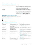
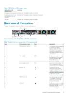
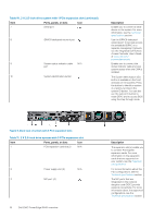
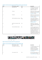
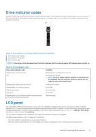
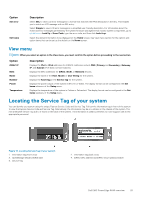
Table 12. 2 X 2.5-inch drive system with 2 PCIe expansion slot (continued) Item Ports, panels, or slots Icon 3 NIC port (4) 4 USB 3.0 port (2) 5 VGA port 6 Serial port 7 iDRAC9 dedicated network port 8 System status indicator cable N/A port 9 System identification button Description The NIC ports that are integrated on the network daughter card (NDC) provide network connectivity. For more information about the supported configurations, see the Technical specifications section. The USB ports are 9-pin and 3.0-compliant. These ports enable you to connect USB devices to the system. Enables you to connect a display device to the system. For more information, see the Technical specifications section. Enables you to connect a serial device to the system. For more information, see the Technical specifications section. Use the iDRAC9 dedicated network port to securely access the embedded iDRAC on a separate management network, see the www.dell.com/ poweredgemanuals Enables you to connect the status indicator cable and view system status when the CMA is installed. The System Identification (ID) button is available on the front and back of the systems. Press the button to identify a system in a rack by turning on the system ID button. You can also use the system ID button to reset iDRAC and to access BIOS using the step through mode. NIC indicator codes Each NIC on the back of the system has indicators that provide information about the activity and link status. The activity LED indicator indicates if data is flowing through the NIC, and the link LED indicator indicates the speed of the connected network. Figure 10. NIC indicator codes 1. Link LED indicator 2. Activity LED indicator 20 Dell EMC PowerEdge R640 overview
-
 1
1 -
2
-
3
-
4
-
5
-
6
-
7
-
8
-
9
-
10
-
11
-
12
-
13
-
14
-
 15
15 -
 16
16 -
 17
17 -
 18
18 -
 19
19 -
 20
20 -
 21
21 -
 22
22 -
 23
23 -
 24
24 -
 25
25 -
26
-
27
-
28
-
29
-
30
-
31
-
32
-
33
-
34
-
35
-
36
-
37
-
38
-
39
-
40
-
41
-
42
-
43
-
44
-
45
-
46
-
47
-
48
-
49
-
50
-
51
-
52
-
53
-
54
-
55
-
56
-
57
-
58
-
59
-
60
-
61
-
62
-
63
-
64
-
65
-
66
-
67
-
68
-
69
-
70
-
71
-
72
-
73
-
74
-
75
-
76
-
77
-
78
-
79
-
80
-
81
-
82
-
83
-
84
-
85
-
86
-
87
-
88
-
89
-
90
-
91
-
92
-
93
-
94
-
95
-
96
-
97
-
98
-
99
-
100
-
101
-
102
-
103
-
104
-
105
-
106
-
107
-
108
-
109
-
110
-
111
-
112
-
113
-
114
-
115
-
116
-
117
-
118
-
119
-
120
-
121
-
122
-
123
-
124
-
125
-
126
-
127
-
128
-
129
-
130
-
131
-
132
-
133
-
134
-
135
-
136
-
137
-
138
-
139
-
140
-
141
-
142
-
143
-
144
-
145
-
146
-
147
-
148
-
149
-
150
-
151
-
152
-
153
-
154
-
155
-
156
-
157
-
158
-
159
-
160
-
161
-
162
-
163
-
164
-
165
-
166
-
167
-
168
-
169
-
170
-
171
-
172
-
173
 |
 |
