Dell PowerEdge R640 EMC PowerEdge R640 Installation and Service Manual - Page 85
Inside the system - 3 PCIe expansion risers
 |
View all Dell PowerEdge R640 manuals
Add to My Manuals
Save this manual to your list of manuals |
Page 85 highlights
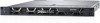
Figure 34. Inside the system - 3 PCIe expansion risers 1. right control panel cable cover 3. backplane cover 5. cabling latch 7. air shroud 9. processor 2 slot 11. expansion riser 2 A 13. expansion riser 1 A 15. integrated storage controller card 17. intrusion switch 19. hard drive backplane 2. hard drive cage 4. backplane release latch 6. cooling fan (8) 8. processor and DIMM blank 10. IDSDM/vFlash module slot 12. network daughter card 14. PCIe shroud 16. processor 1 18. cabling latch 20. left control panel cable cover Installing and removing system components 85
-
 1
1 -
2
-
3
-
4
-
5
-
6
-
7
-
8
-
9
-
10
-
11
-
12
-
13
-
14
-
15
-
16
-
17
-
18
-
19
-
20
-
21
-
22
-
23
-
24
-
25
-
26
-
27
-
28
-
29
-
30
-
31
-
32
-
33
-
34
-
35
-
36
-
37
-
38
-
39
-
40
-
41
-
42
-
43
-
44
-
45
-
46
-
47
-
48
-
49
-
50
-
51
-
52
-
53
-
54
-
55
-
56
-
57
-
58
-
59
-
60
-
61
-
62
-
63
-
64
-
65
-
66
-
67
-
68
-
69
-
70
-
71
-
72
-
73
-
74
-
75
-
76
-
77
-
78
-
79
-
 80
80 -
 81
81 -
 82
82 -
 83
83 -
 84
84 -
 85
85 -
 86
86 -
 87
87 -
 88
88 -
 89
89 -
 90
90 -
91
-
92
-
93
-
94
-
95
-
96
-
97
-
98
-
99
-
100
-
101
-
102
-
103
-
104
-
105
-
106
-
107
-
108
-
109
-
110
-
111
-
112
-
113
-
114
-
115
-
116
-
117
-
118
-
119
-
120
-
121
-
122
-
123
-
124
-
125
-
126
-
127
-
128
-
129
-
130
-
131
-
132
-
133
-
134
-
135
-
136
-
137
-
138
-
139
-
140
-
141
-
142
-
143
-
144
-
145
-
146
-
147
-
148
-
149
-
150
-
151
-
152
-
153
-
154
-
155
-
156
-
157
-
158
-
159
-
160
-
161
-
162
-
163
-
164
-
165
-
166
-
167
-
168
-
169
-
170
-
171
-
172
-
173
 |
 |

Figure 34. Inside the system - 3 PCIe expansion risers
1.
right control panel cable cover
2.
hard drive cage
3.
backplane cover
4.
backplane release latch
5.
cabling latch
6.
cooling fan (8)
7.
air shroud
8.
processor and DIMM blank
9.
processor 2 slot
10.
IDSDM/vFlash module slot
11.
expansion riser 2 A
12.
network daughter card
13.
expansion riser 1 A
14.
PCIe shroud
15.
integrated storage controller card
16.
processor 1
17.
intrusion switch
18.
cabling latch
19.
hard drive backplane
20. left control panel cable cover
Installing and removing system components
85