Dell PowerEdge R640 EMC PowerEdge R640 Installation and Service Manual - Page 159
securing bracket
 |
View all Dell PowerEdge R640 manuals
Add to My Manuals
Save this manual to your list of manuals |
Page 159 highlights
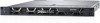
CAUTION: Do not lift the system board by holding a memory module, processor, or other components. CAUTION: Take care not to damage the system identification button while placing the system board into the chassis. 2. Holding the post and release pin, incline the system board, and lower the system board into the chassis. 3. Slide the system board toward the back of the system until the release pin clicks into place. Figure 111. Installing the system board Next steps 1. Replace the following: a. Trusted Platform Module (TPM) b. Integrated storage controller card c. Internal USB key (if applicable) d. USB 3.0 module (if applicable) e. Internal USB key (if applicable) f. All expansion cards and risers g. Processors and heat sink modules h. Processors blanks (if applicable) i. Memory modules and memory module blanks j. Network daughter card k. Air shroud 2. Reconnect all cables to the system board. NOTE: Ensure that the cables inside the system are routed along the chassis wall and secured using the cable securing bracket. 3. Follow the procedure listed in After working inside your system on page 72. 4. Ensure that you: a. Use the Easy Restore feature to restore the Service Tag For more information, see the Restoring the Service Tag by using the Easy Restore feature section. b. If the Service Tag is not backed up in the backup flash device, enter the Service Tag manually. c. Update the BIOS and iDRAC versions. d. Re-enable the Trusted Platform Module (TPM). For more information, see the Upgrading the Trusted Platform Module section. 5. Import your new or existing iDRAC Enterprise license. For more information, see Integrated Dell Remote Access Controller User's Guide, at www.dell.com/poweredgemanuals. Installing and removing system components 159
-
 1
1 -
2
-
3
-
4
-
5
-
6
-
7
-
8
-
9
-
10
-
11
-
12
-
13
-
14
-
15
-
16
-
17
-
18
-
19
-
20
-
21
-
22
-
23
-
24
-
25
-
26
-
27
-
28
-
29
-
30
-
31
-
32
-
33
-
34
-
35
-
36
-
37
-
38
-
39
-
40
-
41
-
42
-
43
-
44
-
45
-
46
-
47
-
48
-
49
-
50
-
51
-
52
-
53
-
54
-
55
-
56
-
57
-
58
-
59
-
60
-
61
-
62
-
63
-
64
-
65
-
66
-
67
-
68
-
69
-
70
-
71
-
72
-
73
-
74
-
75
-
76
-
77
-
78
-
79
-
80
-
81
-
82
-
83
-
84
-
85
-
86
-
87
-
88
-
89
-
90
-
91
-
92
-
93
-
94
-
95
-
96
-
97
-
98
-
99
-
100
-
101
-
102
-
103
-
104
-
105
-
106
-
107
-
108
-
109
-
110
-
111
-
112
-
113
-
114
-
115
-
116
-
117
-
118
-
119
-
120
-
121
-
122
-
123
-
124
-
125
-
126
-
127
-
128
-
129
-
130
-
131
-
132
-
133
-
134
-
135
-
136
-
137
-
138
-
139
-
140
-
141
-
142
-
143
-
144
-
145
-
146
-
147
-
148
-
149
-
150
-
151
-
152
-
153
-
 154
154 -
 155
155 -
 156
156 -
 157
157 -
 158
158 -
 159
159 -
 160
160 -
 161
161 -
 162
162 -
 163
163 -
 164
164 -
165
-
166
-
167
-
168
-
169
-
170
-
171
-
172
-
173
 |
 |
