Dell PowerEdge R640 EMC PowerEdge R640 Installation and Service Manual - Page 107
Installing a processor and heat sink module
 |
View all Dell PowerEdge R640 manuals
Add to My Manuals
Save this manual to your list of manuals |
Page 107 highlights
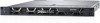
Figure 49. Installing the heat sink onto the processor Next steps 1. Install the processor and heat sink module. 2. Install the air shroud. 3. Follow the procedure listed in After working inside your system on page 72. Installing a processor and heat sink module Prerequisites CAUTION: Never remove the heat sink from a processor unless you intend to replace the processor. The heat sink is necessary to maintain proper thermal conditions. 1. Follow the safety guidelines listed in Safety instructions on page 71. 2. If installed, remove the processor blank and CPU dust cover. Steps 1. Align the pin 1 indicator of the heat sink to the system board and then place the processor and heat sink module (PHM) on the processor socket. CAUTION: To avoid damaging the fins on the heat sink, do not press down on the heat sink fins. NOTE: Ensure that the PHM is held parallel to the system board to prevent damaging the components. 2. Push the blue retention clips inward to allow the heat sink to drop into place. 3. Using the Torx #T30 screwdriver, tighten the screws on the heat sink in the order below: a. Partially tighten the first screw (approximately 3 turns). b. Tighten the second screw completely. c. Return to the first screw and tighten it completely. If the PHM slips off the blue retention clips when the screws are partially tightened, follow these steps to secure the PHM: Installing and removing system components 107
-
 1
1 -
2
-
3
-
4
-
5
-
6
-
7
-
8
-
9
-
10
-
11
-
12
-
13
-
14
-
15
-
16
-
17
-
18
-
19
-
20
-
21
-
22
-
23
-
24
-
25
-
26
-
27
-
28
-
29
-
30
-
31
-
32
-
33
-
34
-
35
-
36
-
37
-
38
-
39
-
40
-
41
-
42
-
43
-
44
-
45
-
46
-
47
-
48
-
49
-
50
-
51
-
52
-
53
-
54
-
55
-
56
-
57
-
58
-
59
-
60
-
61
-
62
-
63
-
64
-
65
-
66
-
67
-
68
-
69
-
70
-
71
-
72
-
73
-
74
-
75
-
76
-
77
-
78
-
79
-
80
-
81
-
82
-
83
-
84
-
85
-
86
-
87
-
88
-
89
-
90
-
91
-
92
-
93
-
94
-
95
-
96
-
97
-
98
-
99
-
100
-
101
-
 102
102 -
 103
103 -
 104
104 -
 105
105 -
 106
106 -
 107
107 -
 108
108 -
 109
109 -
 110
110 -
 111
111 -
 112
112 -
113
-
114
-
115
-
116
-
117
-
118
-
119
-
120
-
121
-
122
-
123
-
124
-
125
-
126
-
127
-
128
-
129
-
130
-
131
-
132
-
133
-
134
-
135
-
136
-
137
-
138
-
139
-
140
-
141
-
142
-
143
-
144
-
145
-
146
-
147
-
148
-
149
-
150
-
151
-
152
-
153
-
154
-
155
-
156
-
157
-
158
-
159
-
160
-
161
-
162
-
163
-
164
-
165
-
166
-
167
-
168
-
169
-
170
-
171
-
172
-
173
 |
 |
