Dell PowerEdge R640 EMC PowerEdge R640 Installation and Service Manual - Page 149
Installing the VGA module
 |
View all Dell PowerEdge R640 manuals
Add to My Manuals
Save this manual to your list of manuals |
Page 149 highlights
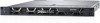
4. Remove the backplane cover. 5. Remove the air shroud. 6. Disconnect the VGA cable from the VGA connector on the system board. For locating the connector, see the System board jumpers and connecters section. NOTE: Ensure that you note the routing of the cables as you remove them from the system board. Route these cables properly when you replace them to prevent them from being pinched or crimped. Steps 1. Using Phillips #1 screwdriver, remove the screw on the VGA module. 2. Slide the module out of the system. Figure 102. Removing the VGA module Next steps 1. Install the VGA module. Installing the VGA module Prerequisites 1. Follow the safety guidelines listed in Safety instructions on page 71. 2. Follow the procedure listed in Before working inside your system on page 72. 3. Remove the front bezel. 4. Remove the backplane cover. 5. Remove the air shroud. NOTE: Ensure that you note the routing of the cables as you remove them from the system board. Route these cables properly when you replace them to prevent them from being pinched or crimped. Steps 1. Route the VGA cable through the VGA module slot on the front of the system and slide the VGA module into the slot. 2. Align the hole on the module with the screw hole on the system. 3. Using the Phillips #1 screwdriver, secure the VGA module to the system with the screw. Installing and removing system components 149
-
 1
1 -
2
-
3
-
4
-
5
-
6
-
7
-
8
-
9
-
10
-
11
-
12
-
13
-
14
-
15
-
16
-
17
-
18
-
19
-
20
-
21
-
22
-
23
-
24
-
25
-
26
-
27
-
28
-
29
-
30
-
31
-
32
-
33
-
34
-
35
-
36
-
37
-
38
-
39
-
40
-
41
-
42
-
43
-
44
-
45
-
46
-
47
-
48
-
49
-
50
-
51
-
52
-
53
-
54
-
55
-
56
-
57
-
58
-
59
-
60
-
61
-
62
-
63
-
64
-
65
-
66
-
67
-
68
-
69
-
70
-
71
-
72
-
73
-
74
-
75
-
76
-
77
-
78
-
79
-
80
-
81
-
82
-
83
-
84
-
85
-
86
-
87
-
88
-
89
-
90
-
91
-
92
-
93
-
94
-
95
-
96
-
97
-
98
-
99
-
100
-
101
-
102
-
103
-
104
-
105
-
106
-
107
-
108
-
109
-
110
-
111
-
112
-
113
-
114
-
115
-
116
-
117
-
118
-
119
-
120
-
121
-
122
-
123
-
124
-
125
-
126
-
127
-
128
-
129
-
130
-
131
-
132
-
133
-
134
-
135
-
136
-
137
-
138
-
139
-
140
-
141
-
142
-
143
-
 144
144 -
 145
145 -
 146
146 -
 147
147 -
 148
148 -
 149
149 -
 150
150 -
 151
151 -
 152
152 -
 153
153 -
 154
154 -
155
-
156
-
157
-
158
-
159
-
160
-
161
-
162
-
163
-
164
-
165
-
166
-
167
-
168
-
169
-
170
-
171
-
172
-
173
 |
 |
