Dell PowerEdge T110 Hardware Owner's Manual
Dell PowerEdge T110 Manual
 |
View all Dell PowerEdge T110 manuals
Add to My Manuals
Save this manual to your list of manuals |
Dell PowerEdge T110 manual content summary:
- Dell PowerEdge T110 | Hardware Owner's Manual - Page 1
Dell™ PowerEdge™ T110 Systems Hardware Owner's Manual - Dell PowerEdge T110 | Hardware Owner's Manual - Page 2
indicates potential damage to hardware or loss of data if instructions are not followed. WARNING: A WARNING indicates a potential for Dell Inc. is strictly forbidden. Trademarks used in this text: Dell, the DELL logo, and PowerEdge are trademarks of Dell Inc.; Microsoft, Windows, Windows Server - Dell PowerEdge T110 | Hardware Owner's Manual - Page 3
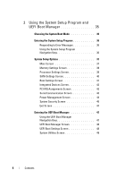
About Your System 11 Accessing System Features During Startup 11 Front-Panel Features and Indicators 12 Back-Panel Features and Indicators 14 Guidelines for Connecting External Devices 15 NIC Indicator Codes 16 Power Selection 17 Diagnostic Lights 18 System Messages 20 Warning Messages 33 - Dell PowerEdge T110 | Hardware Owner's Manual - Page 4
Program 36 Responding to Error Messages 36 Using the System Setup Program Navigation Keys 36 System Setup Options 37 Main Screen 37 Memory Settings Screen 39 Processor Settings Screen 39 SATA Settings Screen 40 Boot Settings Screen 41 Integrated Devices Screen 42 PCI IRQ Assignments Screen - Dell PowerEdge T110 | Hardware Owner's Manual - Page 5
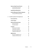
Controller Configuration . . . . 54 Entering the BMC Setup Module 54 3 Installing System Components 55 Recommended Tools 55 Inside the System 56 Opening and Closing the System 57 Opening the System 57 Closing the System 58 Front Bezel 59 Removing the Front Bezel 59 Installing the Front - Dell PowerEdge T110 | Hardware Owner's Manual - Page 6
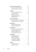
63 Removing an Optical or Tape Drive 63 Installing an Optical or Tape Drive 66 Hard Drives 68 Hard Drive Installation Guidelines 68 Removing a Hard Drive 68 Installing a Hard Drive 70 Removing a Hard Drive from a Hard-Drive Bracket 71 Expansion Card Stabilizer 72 Removing the Expansion - Dell PowerEdge T110 | Hardware Owner's Manual - Page 7
System Board 101 Installing the System Board 102 4 Troubleshooting Your System 105 Safety First-For You and Your System 105 Troubleshooting System Startup Failure 105 Troubleshooting External Connections 105 Troubleshooting the Video Subsystem 106 Troubleshooting a USB Device 106 Contents - Dell PowerEdge T110 | Hardware Owner's Manual - Page 8
Memory 113 Troubleshooting an Internal USB Key 114 Troubleshooting an Optical Drive 115 Troubleshooting a Tape Backup Unit 116 Troubleshooting a Hard Drive 117 Troubleshooting Expansion Cards 118 Troubleshooting the Processor 119 5 Running the System Diagnostics 121 Using Online Diagnostics - Dell PowerEdge T110 | Hardware Owner's Manual - Page 9
Devices for Testing 123 Selecting Diagnostics Options 123 Viewing Information and Results 124 6 Jumpers and Connectors 125 System Board Jumper 125 System Board Connectors 126 Disabling a Forgotten Password 128 7 Getting Help 129 Contacting Dell 129 Glossary 131 Index 139 Contents - Dell PowerEdge T110 | Hardware Owner's Manual - Page 10
10 Contents - Dell PowerEdge T110 | Hardware Owner's Manual - Page 11
System Setup Program and UEFI Boot Manager" on page 35. Enters System Services, which opens the Unified Server Configurator (USC). The USC allows you to access utilities such as embedded system diagnostics. For more information, see the USC documentation. Enters the BIOS Boot Manager - Dell PowerEdge T110 | Hardware Owner's Manual - Page 12
the DC power supply output to the system. NOTE: When powering on the system, the video monitor can take from several seconds to over 2 minutes to display an image, depending on the amount of memory installed in the system. NOTE: On ACPI-compliant operating systems, turning off the system using the - Dell PowerEdge T110 | Hardware Owner's Manual - Page 13
3 Hard drive activity indicator 4 USB connectors (2) 5 Diagnostic indicator lights (4) 6 Tape drive (optional) 7 Optical drive (optional) Description The system health indicator blinks amber when a system fault is detected. The hard drive activity indicator lights up when the hard drive - Dell PowerEdge T110 | Hardware Owner's Manual - Page 14
Features and Indicators Figure 1-2. Back-Panel Features and Indicators 1 2 3 4 5 6 7 8 9 10 11 Item Indicator, Button, or Icon Connector 1 Padlock ring 2 Security cable slot 3 Voltage selection switch Description Locks the cover release latch - Dell PowerEdge T110 | Hardware Owner's Manual - Page 15
the device specifies otherwise). • Ensure that the appropriate driver for the attached device has been installed on the system. • If necessary to enable ports on your system, use the System Setup program. See "Using the System Setup Program and UEFI Boot Manager" on page 35. About Your System 15 - Dell PowerEdge T110 | Hardware Owner's Manual - Page 16
NIC Indicator Codes 1 2 1 link indicator 2 activity indicator Indicator Link and activity indicators are off Link indicator is green Link indicator is amber Activity indicator is green blinking Indicator Code The NIC is not connected to the network. The NIC is connected to a valid network link - Dell PowerEdge T110 | Hardware Owner's Manual - Page 17
Power Selection The voltage selection switch on the back panel of the system allows you to select one of two primary voltage inputs. Figure 1-4. Power Selection Switch CAUTION: Be sure to set the voltage selection - Dell PowerEdge T110 | Hardware Owner's Manual - Page 18
Diagnostic Lights The four diagnostic indicator lights on the system front panel display error codes during system startup. Table 1-2 lists the causes and possible corrective actions associated with these codes. A highlighted circle indicates the light is on; a non-highlighted circle indicates the - Dell PowerEdge T110 | Hardware Owner's Manual - Page 19
connected. See "Hard Drives" on page 68 for information on the drives installed in your system. See "Troubleshooting a USB Device" on page 106. See "Troubleshooting System Memory" on page 113. See "Getting Help" on page 129. Memory configuration See "Troubleshooting System error. Memory" on page - Dell PowerEdge T110 | Hardware Owner's Manual - Page 20
to notify you of a possible problem with the system. NOTE: If Wait for the system to reboot. responding to BIOS communication either because it is not functioning properly required may exceed PSU wattage. Alert! Continuing system boot accepts the risk that system may power down without warning - Dell PowerEdge T110 | Hardware Owner's Manual - Page 21
power down without warning. The system configuration If any system components of processor, memory were just upgraded, return the modules, and expansion system to the previous cards may not be supported configuration. If the system by the power supply. boots without this warning, then the - Dell PowerEdge T110 | Hardware Owner's Manual - Page 22
Program and available. Use UEFI Boot Manager" on the system setup page 35. program to change the boot mode as needed. Decreasing available memory. Faulty or improperly Reseat the memory modules. installed memory modules. See "Troubleshooting System Memory" on page 113. Embedded NICx - Dell PowerEdge T110 | Hardware Owner's Manual - Page 23
the mouse or keyboard is operational. See "Troubleshooting a USB Device" on page 106. Gate A20 failure. specific information. Note the information, and take the appropriate action to resolve the problem. Invalid configuration information please run SETUP program. An invalid system configuration - Dell PowerEdge T110 | Hardware Owner's Manual - Page 24
the USB port(s). See "Entering the System Setup Program" on page 36. Manufacturing mode detected. System is in manufacturing Reboot to take the system out mode. of manufacturing mode. Maximum rank count exceeded. The following DIMM has been disabled: x Invalid memory configuration. The - Dell PowerEdge T110 | Hardware Owner's Manual - Page 25
causes. The current memory configuration may support only the minimum frequency. Ensure that your memory configuration supports the higher frequency. See "General Memory Module Installation Guidelines" on page 80. Memory tests terminated by keystroke. POST memory test was Information only - Dell PowerEdge T110 | Hardware Owner's Manual - Page 26
hard drive. If the problem or hard-drive subsystem, or persists, see "Troubleshooting no bootable USB key a USB Device" on page 106, installed. "Troubleshooting an Optical Drive" on page 115, and "Troubleshooting a Hard Drive" on page 117. See "Using the System Setup Program and UEFI Boot - Dell PowerEdge T110 | Hardware Owner's Manual - Page 27
the problem persists, see "Troubleshooting Expansion Cards" on page 118. Quad rank DIMM detected after single rank or dual rank DIMM in socket. Invalid memory configuration. Ensure that the memory modules are installed in a valid configuration. See "General Memory Module Installation Guidelines - Dell PowerEdge T110 | Hardware Owner's Manual - Page 28
cables are properly connected. See "Troubleshooting a USB Device" on page 106 or "Troubleshooting a Hard Drive" on page 117 for the appropriate drive(s) installed in your system. Shutdown failure. General system error. See "Getting Help" on page 129. The amount of Memory has been added or If - Dell PowerEdge T110 | Hardware Owner's Manual - Page 29
sensor is installed See "System Memory" on in the specified memory page 80. slot. Time-of-day clock stopped. Faulty battery or faulty chip. See "Troubleshooting the System Battery" on page 110. Time-of-day not Incorrect Time or Date set - please run settings; faulty system SETUP program. battery - Dell PowerEdge T110 | Hardware Owner's Manual - Page 30
System Services image is either corrupted in the system firmware or has been lost due to system board replacement. Restart the system and update the memory Reseat the memory modules. modules or faulty keyboard See "Troubleshooting System or mouse controller chip. Memory" on page 113. If the problem - Dell PowerEdge T110 | Hardware Owner's Manual - Page 31
connection. Install the control panel, or check the cable connections between the display module, the control panel board, and the system board. See "Control Panel Assembly" on page 98. Warning! No micro Micro code update failed. code update loaded for processor n. Update the BIOS firmware. See - Dell PowerEdge T110 | Hardware Owner's Manual - Page 32
installed in a valid configuration. See "General Memory Module Installation Guidelines" on page 80. If the problem persists, see "Troubleshooting System Memory" on page 113. Write fault. Write fault on selected drive. Faulty USB device, USB medium, optical drive assembly, hard drive, or hard-drive - Dell PowerEdge T110 | Hardware Owner's Manual - Page 33
and tools for configuring and managing your system, including those pertaining to the operating system, system management software, system updates, and system components that you purchased with your system. NOTE: Always check for updates on support.dell.com/manuals and read the updates first because - Dell PowerEdge T110 | Hardware Owner's Manual - Page 34
34 About Your System - Dell PowerEdge T110 | Hardware Owner's Manual - Page 35
systems must be UEFI-compatible (for example, Microsoft® Windows Server® 2008 x64 version) to be installed from the UEFI boot mode. DOS and 32-bit operating systems do not support UEFI and can only be installed from the BIOS boot mode. Using the System Setup Program and UEFI Boot Manager 35 - Dell PowerEdge T110 | Hardware Owner's Manual - Page 36
: = System Setup If your operating system begins to load before you press , allow the system to finish booting, and then restart your After installing a memory upgrade, it is normal for your system to display a message the first time you start your system. Using the System Setup Program - Dell PowerEdge T110 | Hardware Owner's Manual - Page 37
Options Main Screen NOTE: The options for the System Setup program change based on the system configuration. NOTE: The System Setup program defaults are listed under their respective options in the following sections, where applicable. Option System Time System Date Description Sets the time - Dell PowerEdge T110 | Hardware Owner's Manual - Page 38
boot mode (BIOS or UEFI). For BIOS boot mode, you can also specify the boot devices. See "Boot and any installed expansion card that requires memory modules with preconfigured or customized settings. See "Power Management Screen" on page 44. Displays a screen to configure the system password and setup - Dell PowerEdge T110 | Hardware Owner's Manual - Page 39
. Displays the system memory speed. Displays the amount of video memory. Specifies whether system memory tests are run at system boot. Options are Enabled and Disabled. Processor Settings Screen Option 64-bit Core Speed Bus Speed Description Specifies if the processor supports 64-bit extensions - Dell PowerEdge T110 | Hardware Owner's Manual - Page 40
or disables Execute Disable Memory Protection Technology. Number of Cores per Processor (All default) If set to All, the maximum number of cores , ATA, AHCI, or RAID modes. NOTE: The UEFI support is disabled if SATA is set to the RAID mode. 40 Using the System Setup Program and UEFI Boot Manager - Dell PowerEdge T110 | Hardware Owner's Manual - Page 41
operating system supports Unified Extensible Firmware Interface, you can set this option to UEFI. Setting this field to BIOS allows compatibility with nonUEFI operating systems. NOTE: Setting this field to UEFI disables the Boot Sequence, Hard-Disk Drive Sequence, and USB Flash Drive Emulation Type - Dell PowerEdge T110 | Hardware Owner's Manual - Page 42
the USB flash drive to act as a hard drive. Floppy allows the USB flash drive to act as a removable diskette drive. Auto automatically chooses the appropriate emulation type for the device. If you install a device in this slot that is configured as a removable diskette drive, you must manually set - Dell PowerEdge T110 | Hardware Owner's Manual - Page 43
Enables or disables BIOS support for the integrated video controller. NOTE: This field can be disabled only if an add-in video card is present. redirection by SOL, configure the same port address for console redirection and the serial device. Using the System Setup Program and UEFI Boot Manager 43 - Dell PowerEdge T110 | Hardware Owner's Manual - Page 44
, the fan power to Minimum Power, and the memory power to Maximum Performance. The BIOS sets the processor performance based on processor utilization. • Maximum Performance sets all fields to Maximum Performance. If you select Custom, you can configure each option independently. Options are OS DBPM - Dell PowerEdge T110 | Hardware Owner's Manual - Page 45
Power and Performance Management Memory Power and Performance Management Description Options are Maximum Performance or Minimum Power. Options are Maximum Performance, a specified frequency, or Minimum Power. System Security Screen Option System Password Setup Password Password Status (Unlocked - Dell PowerEdge T110 | Hardware Owner's Manual - Page 46
to Off. CAUTION: Clearing the TPM will lose all encryption keys in the TPM. This option prevents booting to the operating system and results in data loss if the encryption keys cannot be restored. Back up Recovery Delay is set to User Defined. 46 Using the System Setup Program and UEFI Boot Manager - Dell PowerEdge T110 | Hardware Owner's Manual - Page 47
, Microsoft® Windows Server® 2008 x64 version) to be installed from the UEFI boot mode. DOS and 32-bit operating systems can only be installed from the BIOS boot mode. NOTE: The Boot Mode must be set to UEFI in the System Setup program to access the UEFI Boot Manager. The UEFI Boot Manager enables - Dell PowerEdge T110 | Hardware Owner's Manual - Page 48
you to access the System Setup program, System Services (Unified Server Configurator [USC]), Diagnostics, and BIOS-level boot options. UEFI Boot Settings Screen Option Add Boot Option Delete Boot Option Enable/Disable Boot Option Change Boot Order Description Adds a new boot option. Deletes an - Dell PowerEdge T110 | Hardware Owner's Manual - Page 49
Screen Option System Setup System Services (USC) BIOS Boot Manager Reboot System Description Accesses the System Setup program without rebooting. Restarts the system and accesses the USC, which allows you to run utilities such as system diagnostics. Accesses the BIOS-level boot options list - Dell PowerEdge T110 | Hardware Owner's Manual - Page 50
Before assigning a system password, enter the System Setup program and check the System Password option. When a second time and press . System Password changes to Enabled. Exit the System Setup program and begin using your system. 6 Either reboot the system now for the password protection - Dell PowerEdge T110 | Hardware Owner's Manual - Page 51
> to access the setup password window. Press twice to clear the existing setup password. 3 The setting changes to Not Enabled. 4 If you want to assign a new setup password, perform the steps in "Assigning a Setup Password" on page 52. Using the System Setup Program and UEFI Boot Manager 51 - Dell PowerEdge T110 | Hardware Owner's Manual - Page 52
setup password can be the same as the system password. If the two passwords are different, the setup the setup Setup Password Enabled If Setup Password is Enabled, you must enter the correct setup password before modifying most of the System Setup modify, the System Setup screens. The following - Dell PowerEdge T110 | Hardware Owner's Manual - Page 53
and other peripherals For more information about setting up USC, configuring hardware and firmware, and deploying the operating system, see the Unified Server Configurator documentation on the Dell Support website at support.dell.com/manuals. Using the System Setup Program and UEFI Boot Manager 53 - Dell PowerEdge T110 | Hardware Owner's Manual - Page 54
Controller Configuration The BMC enables configuring, 's operating system • Provides text console redirection for system setup, text-based utilities, and operating system consoles NOTE: the BMC and systems management applications. Entering the BMC Setup Module 1 Turn on or restart your system. 2 - Dell PowerEdge T110 | Hardware Owner's Manual - Page 55
Installing System Components Recommended Tools You may need the following items to perform the procedures in this section: • Key to the system keylock • #2 Phillips screwdriver • Wrist grounding strap Installing System Components 55 - Dell PowerEdge T110 | Hardware Owner's Manual - Page 56
only perform troubleshooting and simple repairs as authorized in your product documentation, or as directed by the online or telephone service and support team. Damage due to servicing that is not authorized by Dell is not covered by your warranty. Read and follow the safety instructions that came - Dell PowerEdge T110 | Hardware Owner's Manual - Page 57
only perform troubleshooting and simple repairs as authorized in your product documentation, or as directed by the online or telephone service and support team. Damage due to servicing that is not authorized by Dell is not covered by your warranty. Read and follow the safety instructions that came - Dell PowerEdge T110 | Hardware Owner's Manual - Page 58
system upright on a flat, stable surface. 4 Reattach any peripherals and connect the system to an electrical outlet. 5 Turn on the system and attached peripherals. 58 Installing System Components - Dell PowerEdge T110 | Hardware Owner's Manual - Page 59
only perform troubleshooting and simple repairs as authorized in your product documentation, or as directed by the online or telephone service and support team. Damage due to servicing that is not authorized by Dell is not covered by your warranty. Read and follow the safety instructions that came - Dell PowerEdge T110 | Hardware Owner's Manual - Page 60
bezel with the slots on the chassis. See Figure 3-3. 2 Snap the bezel into place. Removing Front Bezel Insert NOTE: Before installing a drive in one or more of the front drive bays, remove the corresponding insert(s) on the front bezel. 1 From the back of the bezel, push the tab on the end of the - Dell PowerEdge T110 | Hardware Owner's Manual - Page 61
into place. See Figure 3-4. EMI Filler Panel Depending on the configuration of your system, an electromagnetic interference (EMI) filler panel may be installed in one or more of the 5.25inch optical drive bays at the front of the system. EMI filler panels are essential for airflow efficiency and - Dell PowerEdge T110 | Hardware Owner's Manual - Page 62
and Installing the EMI Filler Panel 1 2 3 4 1 drive release latch 3 EMI filler panel 2 shoulder screws (2) 4 tab Installing an EMI Filler Panel 1 Gently slide the EMI filler panel into the bay until it clicks into place. See Figure 3-5. 2 Replace the front bezel. See "Installing the Front Bezel - Dell PowerEdge T110 | Hardware Owner's Manual - Page 63
only perform troubleshooting and simple repairs as authorized in your product documentation, or as directed by the online or telephone service and support team. Damage due to servicing that is not authorized by Dell is not covered by your warranty. Read and follow the safety instructions that came - Dell PowerEdge T110 | Hardware Owner's Manual - Page 64
Figure 3-6. Removing and Installing a Tape Drive (SCSI Connection) 1 2 3 6 5 4 1 power cable 3 drive release latch 5 tape drive 2 data cable 4 drive bay screw slots 6 tape drive shoulder screws (3) 64 Installing System Components - Dell PowerEdge T110 | Hardware Owner's Manual - Page 65
If you are installing another drive in the bay, see "Installing an Optical or Tape Drive" on page 66. 8 If the drive is being permanently removed, install an insert on the front bezel. See "Installing Front Bezel Insert" on page 61. 9 Replace the front bezel. See "Installing the Front Bezel" on page - Dell PowerEdge T110 | Hardware Owner's Manual - Page 66
by the online or telephone service and support team. Damage due to servicing that is not authorized by Dell is not covered by your warranty. Read and follow the safety instructions that came with the product. 1 Unpack the drive and prepare it for installation. For instructions, see the documentation - Dell PowerEdge T110 | Hardware Owner's Manual - Page 67
, connect the SCSI interface cable in the drive kit from the SCSI controller card to the drive. 12 Check all cable connections, and fold cables out of the way to allow for airflow between the fan and cooling vents. 13 Replace the front bezel. See "Installing the Front Bezel" on page 60. 14 Close the - Dell PowerEdge T110 | Hardware Owner's Manual - Page 68
3.5-inch SATA or SAS hard drives in internal drive bays. All the drives must be either SAS or SATA; mixed configurations are not supported. Removing a Hard Drive CAUTION: Many repairs may only be done by a certified service technician. You should only perform troubleshooting and simple repairs as - Dell PowerEdge T110 | Hardware Owner's Manual - Page 69
or Installing a Hard Drive 2 3 1 4 1 hard drive 3 tabs (2) 2 power/data cable 4 hard drive bracket NOTE: If you are not replacing the hard drive, remove the drive from the drive bracket (see Figure 3-11) and insert the empty bracket back into the drive bay. 5 Detach the hard-drive bracket - Dell PowerEdge T110 | Hardware Owner's Manual - Page 70
Installing a Hard Drive CAUTION: Many repairs may only be done by a certified service technician. You should only perform troubleshooting and simple repairs as authorized in your product documentation, or as directed by the online or telephone service and support team. Damage due to servicing that - Dell PowerEdge T110 | Hardware Owner's Manual - Page 71
the System Setup program and reboot the system. 13 Partition and logically format the drive. See the documentation that came with the drive for instructions on installing any software required for drive operation. Removing a Hard Drive from a Hard-Drive Bracket Detach the hard-drive bracket from - Dell PowerEdge T110 | Hardware Owner's Manual - Page 72
Figure 3-11. Removing or Installing a Hard Drive From a Hard Drive Bracket 1 2 1 hard drive 3 blue tabs (2) 3 2 hard drive bracket Expansion Card Stabilizer Removing the Expansion Card Stabilizer 1 Turn off the system and attached peripherals. Disconnect the system from the electrical outlet - Dell PowerEdge T110 | Hardware Owner's Manual - Page 73
only perform troubleshooting and simple repairs as authorized in your product documentation, or as directed by the online or telephone service and support team. Damage due to servicing that is not authorized by Dell is not covered by your warranty. Read and follow the safety instructions that came - Dell PowerEdge T110 | Hardware Owner's Manual - Page 74
the Cooling Shroud 1 2 3 4 1 cooling shroud 3 release tab 2 expansion card stabilizer 4 cooling shroud touch points (2) Installing the Cooling Shroud 1 Align the holes on the cooling shroud with the alignment guides on the system fan. 2 Hold the touch points on the cooling shroud and - Dell PowerEdge T110 | Hardware Owner's Manual - Page 75
cooling, no more than two of the four expansion cards can have a power consumption of greater than 15 W (up to 25 W maximum each), not including the integrated storage controller. • Table 3-1 provides a guide for installing expansion cards to ensure proper cooling and mechanical fit. The expansion - Dell PowerEdge T110 | Hardware Owner's Manual - Page 76
Refer to the expansion card documentation to ensure that the maximum power does not exceed 15 W. 3. When available. See Figure 6-1 for the location of the expansion card slots. NOTE: Your system supports only one RAID card. You can install either of the above mentioned RAID cards in Slot 1. The size - Dell PowerEdge T110 | Hardware Owner's Manual - Page 77
. See "Installing the Expansion Card Stabilizer" on page 72. 9 Close the system. See "Closing the System" on page 58. 10 Reconnect the system and peripherals to their power sources, and turn them on. 11 Remove the card's device driver from the operating system. Installing System Components - Dell PowerEdge T110 | Hardware Owner's Manual - Page 78
card stabilizer 4 release tab Installing an Expansion Card CAUTION: Many repairs may only be done by a certified service technician. You should only perform troubleshooting and simple repairs as authorized in your product documentation, or as directed by the online or telephone service and support - Dell PowerEdge T110 | Hardware Owner's Manual - Page 79
. SAS Controller Expansion Card Read the installation instructions in the documentation for your SAS controller card. Install the card in the expansion card connector (see "Installing an Expansion Card" on page 78), and connect the hard-drive activity indicator cable from the card to the HD_ACT_CARD - Dell PowerEdge T110 | Hardware Owner's Manual - Page 80
the speed of the slowest installed memory module(s). Mode-Specific Guidelines Your system supports both single-channel and dual-channel mode. A minimal single-channel configuration of one 1-GB memory module is also supported in this mode. Table 3-2 shows sample memory configurations that follow the - Dell PowerEdge T110 | Hardware Owner's Manual - Page 81
Sample UDIMM Memory Configurations Memory Module Size 1 1-GB X X X 2-GB X X X 4-GB X X X Memory Sockets 2 3 4 X X X X X X X X X X X X Single Processor Physical Available Memory (GB) Memory (GB) 1 all 2 4 2 all 4 8 4 all 8 16 Installing System Components - Dell PowerEdge T110 | Hardware Owner's Manual - Page 82
or telephone service and support team. Damage due to servicing that is not authorized by Dell is not covered by your warranty. Read and follow the safety instructions that came with the product. CAUTION: To ensure proper system cooling, memory-module blanks must be installed in any memory socket - Dell PowerEdge T110 | Hardware Owner's Manual - Page 83
or telephone service and support team. Damage due to servicing that is not authorized by Dell is not covered by your warranty. Read and follow the safety instructions that came with the product. CAUTION: To ensure proper system cooling, memory-module blanks must be installed in any memory socket - Dell PowerEdge T110 | Hardware Owner's Manual - Page 84
the levers on the other sockets that have memory modules installed. 11 Repeat step 6 through step 10 of this procedure to install the remaining memory modules. See Table 3-2. 12 Replace the expansion card stabilizer. See "Installing the Expansion Card Stabilizer" on page 72. 13 Replace the cooling - Dell PowerEdge T110 | Hardware Owner's Manual - Page 85
your warranty. Read and follow the safety instructions that came with the product. 1 Prior to upgrading your system, download the latest system BIOS version from support.dell.com and follow the instructions included in the compressed download file to install the update on your system. 2 Turn off the - Dell PowerEdge T110 | Hardware Owner's Manual - Page 86
Gently lift the heat sink off of the processor and set the heat sink aside upside down (thermal grease side facing up). Figure 3-15. Installing and Removing the Heat Sink 1 2 1 heat sink 2 heat sink retention screws (4) CAUTION: The processor is held in its socket under strong pressure. Be aware - Dell PowerEdge T110 | Hardware Owner's Manual - Page 87
and out of the way. See Figure 3-16. Figure 3-16. Removing a Processor 2 1 1 socket-release lever 3 notches in processor (2) 5 ZIF socket 3 4 5 6 2 processor 4 processor shield 6 socket keys (2) Installing System Components 87 - Dell PowerEdge T110 | Hardware Owner's Manual - Page 88
, align the processor with the socket keys and set the processor lightly in the socket. CAUTION: Do not use force to seat the processor cooling shroud. See "Installing the Cooling Shroud" on page 74. 11 Replace the expansion card stabilizer. See "Installing the Expansion Card Stabilizer" on page - Dell PowerEdge T110 | Hardware Owner's Manual - Page 89
only perform troubleshooting and simple repairs as authorized in your product documentation, or as directed by the online or telephone service and support team. Damage due to servicing that is not authorized by Dell is not covered by your warranty. Read and follow the safety instructions that came - Dell PowerEdge T110 | Hardware Owner's Manual - Page 90
only perform troubleshooting and simple repairs as authorized in your product documentation, or as directed by the online or telephone service and support team. Damage due to servicing that is not authorized by Dell is not covered by your warranty. Read and follow the safety instructions that came - Dell PowerEdge T110 | Hardware Owner's Manual - Page 91
only perform troubleshooting and simple repairs as authorized in your product documentation, or as directed by the online or telephone service and support team. Damage due to servicing that is not authorized by Dell is not covered by your warranty. Read and follow the safety instructions that came - Dell PowerEdge T110 | Hardware Owner's Manual - Page 92
the System Setup program to confirm that the battery is operating properly. See "Using the System Setup Program and UEFI Boot Manager" on page 35. 8 Enter the correct time and date in the System Setup program's Time and Date fields. 9 Exit the System Setup program. 92 Installing System Components - Dell PowerEdge T110 | Hardware Owner's Manual - Page 93
only perform troubleshooting and simple repairs as authorized in your product documentation, or as directed by the online or telephone service and support team. Damage due to servicing that is not authorized by Dell is not covered by your warranty. Read and follow the safety instructions that came - Dell PowerEdge T110 | Hardware Owner's Manual - Page 94
that secure the power supply to the back panel. 5 Secure the I/O panel and SATA cables (if present) to the routing clip on the side of the power supply. 6 Connect all the power cables to the system board and drives. 7 Replace the cooling shroud. See "Installing the Cooling Shroud" on page 74. 94 - Dell PowerEdge T110 | Hardware Owner's Manual - Page 95
Integrated Devices screen of the System Setup program. See "Integrated Devices Screen" on page 42. To boot from the USB memory key, configure the USB memory key with a boot image and then specify the USB memory key in the boot sequence in the System Setup program. Installing System Components 95 - Dell PowerEdge T110 | Hardware Owner's Manual - Page 96
3-20. Removing or Installing a USB Memory Key 1 2 1 USB memory key 2 USB memory key connector Chassis Intrusion Switch Removing the Chassis Intrusion Switch CAUTION: Many repairs may only be done by a certified service technician. You should only perform troubleshooting and simple repairs as - Dell PowerEdge T110 | Hardware Owner's Manual - Page 97
switch and its attached cable from the system. Figure 3-21. Removing and Installing the Chassis Intrusion Switch 1 2 3 1 chassis intrusion switch 3 INTRUSION connector 2 securing bracket notch Installing the Chassis Intrusion Switch 1 Align the chassis intrusion switch with the securing bracket - Dell PowerEdge T110 | Hardware Owner's Manual - Page 98
only perform troubleshooting and simple repairs as authorized in your product documentation, or as directed by the online or telephone service and support team. Damage due to servicing that is not authorized by Dell is not covered by your warranty. Read and follow the safety instructions that came - Dell PowerEdge T110 | Hardware Owner's Manual - Page 99
Lock 1 1 link bracket lock 6 Remove the mounting screw holding the control panel assembly to the front chassis. See Figure 3-23. 7 Lift the control panel assembly out of the system. 8 Disconnect the control panel cable from the control panel assembly: CAUTION: Do not pull on the cable to unseat the - Dell PowerEdge T110 | Hardware Owner's Manual - Page 100
only perform troubleshooting and simple repairs as authorized in your product documentation, or as directed by the online or telephone service and support team. Damage due to servicing that is not authorized by Dell is not covered by your warranty. Read and follow the safety instructions that came - Dell PowerEdge T110 | Hardware Owner's Manual - Page 101
only perform troubleshooting and simple repairs as authorized in your product documentation, or as directed by the online or telephone service and support team. Damage due to servicing that is not authorized by Dell is not covered by your warranty. Read and follow the safety instructions that came - Dell PowerEdge T110 | Hardware Owner's Manual - Page 102
the system board toward the front end of the chassis. CAUTION: Do not lift the system board by grasping a memory module, processor, or other Figure 3-24. Figure 3-24. Removing and Installing the System Board 1 2 1 screws (10) 2 system board Installing the System Board 1 Unpack the new system - Dell PowerEdge T110 | Hardware Owner's Manual - Page 103
grasping a memory module, processor, or other components. 4 Slightly lift up the front of the panel interface cable • Optical/tape drive power cable • System board power cables 10 Install all expansion cards. See "Installing an Expansion Card" on page 78. 11 Replace the cooling fan. See "Installing - Dell PowerEdge T110 | Hardware Owner's Manual - Page 104
104 Installing System Components - Dell PowerEdge T110 | Hardware Owner's Manual - Page 105
and support team. Damage due to servicing that is not authorized by Dell is not covered by your warranty. Read and follow the safety instructions that came with the product. Troubleshooting System Startup Failure If your system halts during startup prior to video output, especially after installing - Dell PowerEdge T110 | Hardware Owner's Manual - Page 106
. See "Using Online Diagnostics" on page 121. If the tests run successfully, the problem is not related to video hardware. If the tests fail, see "Getting Help" on page 129. Troubleshooting a USB Device Use the following steps to troubleshoot a USB keyboard/mouse. For other USB devices, go to step - Dell PowerEdge T110 | Hardware Owner's Manual - Page 107
Turn on the system and the serial device. If the problem is resolved, replace the serial device. If the problem persists, see "Getting Help" on page 129. Troubleshooting a NIC 1 Run the appropriate online diagnostic test. See "Using Online Diagnostics" on page 121. 2 Restart the system and check for - Dell PowerEdge T110 | Hardware Owner's Manual - Page 108
. See "Installing System Components" on page 55. • Hard drives • USB memory key • Cooling shroud and expansion card stabilizer • Expansion cards • Power supply • Cooling fan • Processor and heat sink • Memory modules 4 Let the system dry thoroughly for at least 24 hours. 108 Troubleshooting Your - Dell PowerEdge T110 | Hardware Owner's Manual - Page 109
installed: • Cooling shroud and expansion card stabilizer • Expansion cards • Power supply • Cooling fan • Processor and heat sink • Memory modules • Hard-drive carriers 4 Ensure that all cables are properly connected. 5 Close the system. See "Closing the System" on page 58. Troubleshooting - Dell PowerEdge T110 | Hardware Owner's Manual - Page 110
only perform troubleshooting and simple repairs as authorized in your product documentation, or as directed by the online or telephone service and support team. Damage due to servicing that is not authorized by Dell is not covered by your warranty. Read and follow the safety instructions that came - Dell PowerEdge T110 | Hardware Owner's Manual - Page 111
telephone service and support team. Damage due to servicing that is not authorized by Dell is not covered by your warranty. Read and follow the safety instructions that came with the product. Ensure that none of the following conditions exist: • System cover, cooling shroud, EMI filler panel, memory - Dell PowerEdge T110 | Hardware Owner's Manual - Page 112
only perform troubleshooting and simple repairs as authorized in your product documentation, or as directed by the online or telephone service and support team. Damage due to servicing that is not authorized by Dell is not covered by your warranty. Read and follow the safety instructions that came - Dell PowerEdge T110 | Hardware Owner's Manual - Page 113
due to servicing that is not authorized by Dell is not covered by your warranty. Read and follow the safety instructions that came with the product. NOTE: Invalid memory configurations can cause your system to halt at startup without video output. See "General Memory Module Installation Guidelines - Dell PowerEdge T110 | Hardware Owner's Manual - Page 114
the diagnostic indicators on the front of the system. 16 If the memory problem is still indicated, repeat step 12 through step 15 for each memory module installed. If the problem persists after all memory modules have been checked, see "Getting Help" on page 129. Troubleshooting an Internal USB Key - Dell PowerEdge T110 | Hardware Owner's Manual - Page 115
Damage due to servicing that is not authorized by Dell is not covered by your warranty. Read and follow the safety instructions that came with the product. 1 Try using a different CD or DVD. 2 Enter the System Setup program and ensure that the integrated SATA controller and the drive's SATA port are - Dell PowerEdge T110 | Hardware Owner's Manual - Page 116
for the tape drive for instructions on selecting the SCSI ID number and enabling or disabling termination. 6 Run the appropriate online diagnostics tests. See "Using Online Diagnostics" on page 121. If you cannot resolve the problem, see "Getting Help" on page 129. 116 Troubleshooting Your System - Dell PowerEdge T110 | Hardware Owner's Manual - Page 117
the online or telephone service and support team. Damage due to servicing that is not authorized by Dell is not covered by your warranty. Read and follow the safety instructions that came with the product. CAUTION: This troubleshooting procedure can destroy data stored on the hard drive. Before you - Dell PowerEdge T110 | Hardware Owner's Manual - Page 118
by the online or telephone service and support team. Damage due to servicing that is not authorized by Dell is not covered by your warranty. Read and follow the safety instructions that came with the product. NOTE: When troubleshooting an expansion card, see the documentation for your operating - Dell PowerEdge T110 | Hardware Owner's Manual - Page 119
only perform troubleshooting and simple repairs as authorized in your product documentation, or as directed by the online or telephone service and support team. Damage due to servicing that is not authorized by Dell is not covered by your warranty. Read and follow the safety instructions that came - Dell PowerEdge T110 | Hardware Owner's Manual - Page 120
120 Troubleshooting Your System - Dell PowerEdge T110 | Hardware Owner's Manual - Page 121
as hard drives, physical memory, communications and printer ports, NICs, CMOS, and more. If you are unable to identify the problem using the online diagnostics, then use the embedded system diagnostics. The files required to run the online diagnostics for systems running supported Microsoft® Windows - Dell PowerEdge T110 | Hardware Owner's Manual - Page 122
, you can use the embedded system diagnostics to help identify the problem. Running the Embedded System Diagnostics The embedded system diagnostics program is run from the Unified Server Configurator (USC) screen. CAUTION: Use the embedded system diagnostics to test only your system. Using - Dell PowerEdge T110 | Hardware Owner's Manual - Page 123
- Time stamps the test log. • Test Iterations - Selects the number of times the test is run. • Log output file pathname - Enables you to specify the USB memory key where the test log file is saved. You cannot save the file to a hard drive. Running the System Diagnostics 123 - Dell PowerEdge T110 | Hardware Owner's Manual - Page 124
Information and Results The following tabs in the Customize window provide information about the test and the test results about the currently selected device, component, or test. • Configuration - Displays basic configuration information about the currently selected device. • Parameters - Displays - Dell PowerEdge T110 | Hardware Owner's Manual - Page 125
Description (default) The password feature is enabled (pins 2-4) NVRAM_CLR The password feature is disabled (pins 4-6) (default) The configuration settings are retained at system boot (pins 3-5) The configuration settings are cleared at the next system boot (pins 1-3) Jumpers and Connectors 125 - Dell PowerEdge T110 | Hardware Owner's Manual - Page 126
26 10 25 24 11 23 22 21 20 19 12 18 17 13 16 15 14 Table 6-2. System Board Jumpers and Connectors Item Connector 1 USB 2 SATA_F eSATA 3 COM 4 VGA Description USB connectors (4) eSATA connector serial connector video connector 126 Jumpers and Connectors - Dell PowerEdge T110 | Hardware Owner's Manual - Page 127
x1 half length Auxiliary hard drive LED Internal USB key 1 and 2 Processor Power connector 12V DIMM_B1 memory module DIMM_B2 memory module DIMM_A1 memory module DIMM_A2 memory module Control panel connector SATA drive SATA drive SATA drive SATA drive/optical drive Power connector Intrusion switch - Dell PowerEdge T110 | Hardware Owner's Manual - Page 128
. 7 Turn on the system and attached peripherals. The existing passwords are not disabled (erased) until the system boots with the password jumper plug removed. However, before you assign a new system and/or setup password, you must install the jumper plug. NOTE: If you assign a new system and/or - Dell PowerEdge T110 | Hardware Owner's Manual - Page 129
, or Dell product catalog. Dell provides several online and telephone-based support and service options. Availability varies by country and product, and some services may not be available in your area. To contact Dell for sales, technical support, or customer service issues: 1 Visit support.dell.com - Dell PowerEdge T110 | Hardware Owner's Manual - Page 130
130 Getting Help - Dell PowerEdge T110 | Hardware Owner's Manual - Page 131
CD or USB memory key that is used to start your system if the system does not boot from the hard drive. BTU card that controls the transfer of data between the processor and memory or between the processor and a peripheral device. coprocessor - A chip that relieves the system's processor of specific - Dell PowerEdge T110 | Hardware Owner's Manual - Page 132
memory. A system's RAM is usually made up entirely of DRAM chips. driver - See device driver. DVD - Digital versatile disc or digital video card. F - Fahrenheit. FAT - File allocation table. The file system structure used by MS-DOS® to organize and keep track of file storage. The Microsoft® Windows - Dell PowerEdge T110 | Hardware Owner's Manual - Page 133
A video mode that can be defined as x horizontal by y vertical pixels by z colors. host adapter - A controller that implements communication between the system's bus and the peripheral device, typically a storage device. hot-swap - The ability to insert or install a device, typically a hard drive or - Dell PowerEdge T110 | Hardware Owner's Manual - Page 134
video is displayed and for which the keyboard and mouse are used. LAN - Local area network. A LAN is usually confined to the same building or a few nearby buildings, with all equipment linked by wiring dedicated specifically to the LAN. LCD - Liquid crystal display. LED - Light to hard-drive capacity - Dell PowerEdge T110 | Hardware Owner's Manual - Page 135
memory. Memory that does not lose its contents when you turn off your system. NVRAM is used for maintaining the date, time, and system configuration information. parity - Redundant information that is associated with a block of data. parity stripe - In RAID arrays, a striped hard drive containing - Dell PowerEdge T110 | Hardware Owner's Manual - Page 136
without a hard drive). RAC - Remote access controller. RAID - Redundant array of independent disks. A method of providing data redundancy. Some common implementations of RAID include RAID 0, RAID 1, RAID 5, RAID 10, and RAID 50. See also mirroring and striping. RAM - Random-access memory. The system - Dell PowerEdge T110 | Hardware Owner's Manual - Page 137
connect a modem to the system. service tag - A bar code label on the system used to identify it when you call Dell for technical support. SMART - Self-Monitoring Analysis and Reporting Technology. Allows hard drives to report errors and failures to the system BIOS and then display an error message - Dell PowerEdge T110 | Hardware Owner's Manual - Page 138
of pixels across by the number of pixels up and down. To display a program at a specific graphics resolution, you must install the appropriate video drivers and your monitor must support the resolution. virtualization - The ability via software to share the resources of a single computer across - Dell PowerEdge T110 | Hardware Owner's Manual - Page 139
, 91 BMC configuring, 54 C cable clip, 94 CD drive troubleshooting, 115 CD/DVD drive installing, 66 removing, 63 chassis intrusion switch installing, 97 removing, 96 replacing, 97 closing the system, 58 connectors USB, 12, 14 video, 12, 14 contacting Dell, 129 cooling fan installing, 90 removing - Dell PowerEdge T110 | Hardware Owner's Manual - Page 140
, 36 expansion cards, 75 installing, 78 removing, 76 replacing, 78 troubleshooting, 118 F front bezel insert, 60 removing, 59 replacing, 60 front panel features, 12 front-panel features, 12 G guidelines connecting external devices, 15 memory installation, 80 H hard drive installing, 70 removing - Dell PowerEdge T110 | Hardware Owner's Manual - Page 141
, 94 removing, 93 replacing, 94 processor installing, 88 removing, 85 troubleshooting, 119 R recommended tools, 55 removing CD/DVD drive, 63 chassis intrusion switch, 96 cooling fan, 89 expansion cards, 76 front bezel, 59 hard drive, 68 I/O panel, 98 memory modules, 82 power supply, 93 processor - Dell PowerEdge T110 | Hardware Owner's Manual - Page 142
cooling fan, 90 expansion cards, 78 front bezel, 60 I/O panel, 100 power supply, 94 system battery, 91 system board, 102 S safety, 105 SAS controller card installing, 79 SAS hard drive. See hard drive. SATA hard drive. See hard drive. securing your system, 45, 51 setup password, 52 startup accessing - Dell PowerEdge T110 | Hardware Owner's Manual - Page 143
, 112 damaged system, 109 expansion cards, 118 external connections, 105 hard drive, 117 internal USB key, 114 keyboard, 106 memory, 113 NIC, 107 power supplies, 111 processor, 119 system cooling, 111 system startup failure, 105 video, 106 wet system, 108 troubleshooting, 106 W warning messages, 33 - Dell PowerEdge T110 | Hardware Owner's Manual - Page 144
144 Index
-
 1
1 -
 2
2 -
 3
3 -
 4
4 -
 5
5 -
 6
6 -
 7
7 -
8
-
9
-
10
-
11
-
12
-
13
-
14
-
15
-
16
-
17
-
18
-
19
-
20
-
21
-
22
-
23
-
24
-
25
-
26
-
27
-
28
-
29
-
30
-
31
-
32
-
33
-
34
-
35
-
36
-
37
-
38
-
39
-
40
-
41
-
42
-
43
-
44
-
45
-
46
-
47
-
48
-
49
-
50
-
51
-
52
-
53
-
54
-
55
-
56
-
57
-
58
-
59
-
60
-
61
-
62
-
63
-
64
-
65
-
66
-
67
-
68
-
69
-
70
-
71
-
72
-
73
-
74
-
75
-
76
-
77
-
78
-
79
-
80
-
81
-
82
-
83
-
84
-
85
-
86
-
87
-
88
-
89
-
90
-
91
-
92
-
93
-
94
-
95
-
96
-
97
-
98
-
99
-
100
-
101
-
102
-
103
-
104
-
105
-
106
-
107
-
108
-
109
-
110
-
111
-
112
-
113
-
114
-
115
-
116
-
117
-
118
-
119
-
120
-
121
-
122
-
123
-
124
-
125
-
126
-
127
-
128
-
129
-
130
-
131
-
132
-
133
-
134
-
135
-
136
-
137
-
138
-
139
-
140
-
141
-
142
-
143
-
144
 |
 |

Dell™ PowerEdge™ T110
Systems
Hardware Owner’s
Manual