Dell PowerEdge T110 Hardware Owner's Manual - Page 103
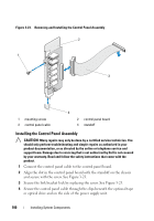
Optical/tape drive power cable, System board power cables
 |
View all Dell PowerEdge T110 manuals
Add to My Manuals
Save this manual to your list of manuals |
Page 103 highlights
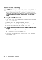
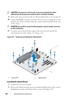
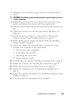
3 Holding the system board by its edges, lower the system board into the chassis. CAUTION: Do not lift the system board by grasping a memory module, processor, or other components. 4 Slightly lift up the front of the system board and maneuver the system board to the bottom of the chassis until it lays completely flat. 5 Push the system board toward the back of the chassis until the board is in place. 6 Tighten the ten screws to secure the system board to the chassis. See Figure 6-1. 7 Transfer the processor to the new system board. See "Removing the Processor" on page 85 and "Installing a Processor" on page 88. 8 Replace all the memory modules and memory blanks. See "Installing Memory Modules" on page 83. 9 Connect the cables in the order listed below (see Figure 6-1 for the locations of the connectors on the system board): • SATA interface cable, if applicable • Control panel interface cable • Optical/tape drive power cable • System board power cables 10 Install all expansion cards. See "Installing an Expansion Card" on page 78. 11 Replace the cooling fan. See "Installing the Cooling Fan" on page 90. 12 Replace the heat sink. See "Installing a Processor" on page 88. 13 Replace the cooling shroud. See "Installing the Cooling Shroud" on page 74. 14 Replace the expansion card stabilizer. See "Installing the Expansion Card Stabilizer" on page 72. 15 Close the system. See "Closing the System" on page 58. Installing System Components 103
-
 1
1 -
2
-
3
-
4
-
5
-
6
-
7
-
8
-
9
-
10
-
11
-
12
-
13
-
14
-
15
-
16
-
17
-
18
-
19
-
20
-
21
-
22
-
23
-
24
-
25
-
26
-
27
-
28
-
29
-
30
-
31
-
32
-
33
-
34
-
35
-
36
-
37
-
38
-
39
-
40
-
41
-
42
-
43
-
44
-
45
-
46
-
47
-
48
-
49
-
50
-
51
-
52
-
53
-
54
-
55
-
56
-
57
-
58
-
59
-
60
-
61
-
62
-
63
-
64
-
65
-
66
-
67
-
68
-
69
-
70
-
71
-
72
-
73
-
74
-
75
-
76
-
77
-
78
-
79
-
80
-
81
-
82
-
83
-
84
-
85
-
86
-
87
-
88
-
89
-
90
-
91
-
92
-
93
-
94
-
95
-
96
-
97
-
 98
98 -
 99
99 -
 100
100 -
 101
101 -
 102
102 -
 103
103 -
 104
104 -
 105
105 -
 106
106 -
 107
107 -
 108
108 -
109
-
110
-
111
-
112
-
113
-
114
-
115
-
116
-
117
-
118
-
119
-
120
-
121
-
122
-
123
-
124
-
125
-
126
-
127
-
128
-
129
-
130
-
131
-
132
-
133
-
134
-
135
-
136
-
137
-
138
-
139
-
140
-
141
-
142
-
143
-
144
 |
 |