Dell PowerEdge T110 Hardware Owner's Manual - Page 84
System, Memory, the memory module socket align with the levers on the other sockets
 |
View all Dell PowerEdge T110 manuals
Add to My Manuals
Save this manual to your list of manuals |
Page 84 highlights
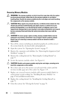
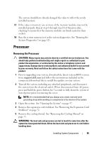
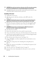
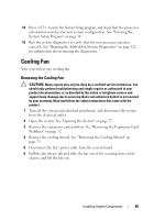
3 Remove the expansion card stabilizer. See "Removing the Expansion Card Stabilizer" on page 72. 4 Remove the cooling shroud. See "Removing the Cooling Shroud" on page 73. 5 Locate the memory module sockets. See Figure 6-1. 6 Remove the memory-module blanks from the sockets in which you plan to install memory modules. 7 Press out the ejectors on each end of the socket until the memory-module blank pops out of the socket. See Figure 3-14. NOTE: Make sure to retain any removed memory-module blanks for future use. 8 Handle each memory module only on either card edge, ensuring not to touch the middle of the memory module. 9 Align the memory module's edge connector with the alignment key of the memory module socket, and insert the memory module in the socket. NOTE: The memory module socket has an alignment key that allows you to install the memory module in the socket in only one way. 10 Press down on the memory module with your thumbs until the socket levers latch into a locked position. When the memory module is properly seated in the socket, the levers on the memory module socket align with the levers on the other sockets that have memory modules installed. 11 Repeat step 6 through step 10 of this procedure to install the remaining memory modules. See Table 3-2. 12 Replace the expansion card stabilizer. See "Installing the Expansion Card Stabilizer" on page 72. 13 Replace the cooling shroud. See "Installing the Cooling Shroud" on page 74. 14 Close the system. See "Closing the System" on page 58. 15 Reconnect the system and peripherals to their power sources, and turn them on. 16 Press to enter the System Setup program, and check the System Memory setting on the main System Setup screen. 84 Installing System Components
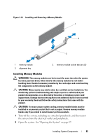
-
 1
1 -
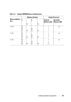
2
-
3
-
4
-
5
-
6
-
7
-
8
-
9
-
10
-
11
-
12
-
13
-
14
-
15
-
16
-
17
-
18
-
19
-
20
-
21
-
22
-
23
-
24
-
25
-
26
-
27
-
28
-
29
-
30
-
31
-
32
-
33
-
34
-
35
-
36
-
37
-
38
-
39
-
40
-
41
-
42
-
43
-
44
-
45
-
46
-
47
-
48
-
49
-
50
-
51
-
52
-
53
-
54
-
55
-
56
-
57
-
58
-
59
-
60
-
61
-
62
-
63
-
64
-
65
-
66
-
67
-
68
-
69
-
70
-
71
-
72
-
73
-
74
-
75
-
76
-
77
-
78
-
 79
79 -
 80
80 -
 81
81 -
 82
82 -
 83
83 -
 84
84 -
 85
85 -
 86
86 -
 87
87 -
 88
88 -
 89
89 -
90
-
91
-
92
-
93
-
94
-
95
-
96
-
97
-
98
-
99
-
100
-
101
-
102
-
103
-
104
-
105
-
106
-
107
-
108
-
109
-
110
-
111
-
112
-
113
-
114
-
115
-
116
-
117
-
118
-
119
-
120
-
121
-
122
-
123
-
124
-
125
-
126
-
127
-
128
-
129
-
130
-
131
-
132
-
133
-
134
-
135
-
136
-
137
-
138
-
139
-
140
-
141
-
142
-
143
-
144
 |
 |