Dell PowerEdge T110 Hardware Owner's Manual - Page 127
Table 6-2., System Board Jumpers and Connectors, Connector, Description, INT_USB1 and INT_USB2
 |
View all Dell PowerEdge T110 manuals
Add to My Manuals
Save this manual to your list of manuals |
Page 127 highlights
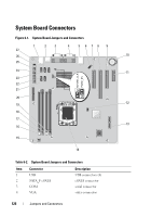
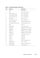
Table 6-2. System Board Jumpers and Connectors Item Connector 5 NIC 6 FAN 7 SLOT1 PCIE_G2_X8 8 SLOT2 PCIE_G2_X8 9 SLOT3 PCIE_G2_X4 10 BATTERY 11 SLOT4 PCIE_G2_X1 12 HD_ACT_CARD 13 INT_USB1 and INT_USB2 14 CPU 15 POWER12V 16 DIMM_B1 17 DIMM_B2 18 DIMM_A1 19 DIMM_A2 20 CTRL_PNL 21 SATA_B 22 SATA_A 23 SATA_C 24 SATA_D 25 PWR_CONN 26 INTRUSION 27 SATA_E ODD Description NIC connector System fan connector PCIe x8 half length PCIe x8 full length PCIe x4 half length Battery socket PCIe x1 half length Auxiliary hard drive LED Internal USB key 1 and 2 Processor Power connector 12V DIMM_B1 memory module DIMM_B2 memory module DIMM_A1 memory module DIMM_A2 memory module Control panel connector SATA drive SATA drive SATA drive SATA drive/optical drive Power connector Intrusion switch connector SATA optical drive Jumpers and Connectors 127
-
 1
1 -
2
-
3
-
4
-
5
-
6
-
7
-
8
-
9
-
10
-
11
-
12
-
13
-
14
-
15
-
16
-
17
-
18
-
19
-
20
-
21
-
22
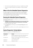
-
23
-
24
-
25
-
26
-
27
-
28
-
29
-
30
-
31
-
32
-
33
-
34
-
35
-
36
-
37
-
38
-
39
-
40
-
41
-
42
-
43
-
44
-
45
-
46
-
47
-
48
-
49
-
50
-
51
-
52
-
53
-
54
-
55
-
56
-
57
-
58
-
59
-
60
-
61
-
62
-
63
-
64
-
65
-
66
-
67
-
68
-
69
-
70
-
71
-
72
-
73
-
74
-
75
-
76
-
77
-
78
-
79
-
80
-
81
-
82
-
83
-
84
-
85
-
86
-
87
-
88
-
89
-
90
-
91
-
92
-
93
-
94
-
95
-
96
-
97
-
98
-
99
-
100
-
101
-
102
-
103
-
104
-
105
-
106
-
107
-
108
-
109
-
110
-
111
-
112
-
113
-
114
-
115
-
116
-
117
-
118
-
119
-
120
-
121
-
 122
122 -
 123
123 -
 124
124 -
 125
125 -
 126
126 -
 127
127 -
 128
128 -
 129
129 -
 130
130 -
 131
131 -
 132
132 -
133
-
134
-
135
-
136
-
137
-
138
-
139
-
140
-
141
-
142
-
143
-
144
 |
 |