Dell PowerEdge T110 Hardware Owner's Manual - Page 88
Installing a Processor, rocessor - lights
 |
View all Dell PowerEdge T110 manuals
Add to My Manuals
Save this manual to your list of manuals |
Page 88 highlights
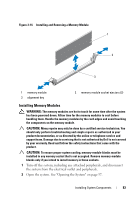
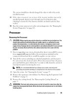
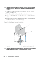
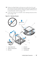
CAUTION: Be careful not to bend any of the pins on the ZIF socket when removing the processor. Bending the pins can permanently damage the system board. 12 Carefully, lift the processor out of the socket and leave the release lever up so that the socket is ready for the new processor. Installing a Processor 1 Unpack the new processor. 2 Align the processor with the socket keys on the ZIF socket. See Figure 3-16. CAUTION: Positioning the processor incorrectly can permanently damage the system board or the processor. Be careful not to bend the pins in the socket. 3 With the release lever on the processor socket in the open position, align the processor with the socket keys and set the processor lightly in the socket. CAUTION: Do not use force to seat the processor. When the processor is positioned correctly, it engages easily into the socket. 4 Close the processor shield. 5 Rotate the socket release lever down until it snaps into place. 6 Using a clean lint-free cloth, remove the thermal grease from the heat sink. 7 Open the grease packet included with your processor kit and apply thermal grease evenly to the top of the new processor. 8 Place the heat sink on the processor. See Figure 3-16. 9 Using a #2 Phillips screwdriver, tighten the heat-sink retention screws. See Figure 3-15. 10 Replace the cooling shroud. See "Installing the Cooling Shroud" on page 74. 11 Replace the expansion card stabilizer. See "Installing the Expansion Card Stabilizer" on page 72. 12 Close the system. See "Closing the System" on page 58. 13 Reconnect the system and peripherals to their power sources, and turn them on. 88 Installing System Components
-
 1
1 -
2
-
3
-
4
-
5
-
6
-
7
-
8
-
9
-
10
-
11
-
12
-
13
-
14
-
15
-
16
-
17
-
18
-
19
-
20
-
21
-
22
-
23
-
24
-
25
-
26
-
27
-
28
-
29
-
30
-
31
-
32
-
33
-
34
-
35
-
36
-
37
-
38
-
39
-
40
-
41
-
42
-
43
-
44
-
45
-
46
-
47
-
48
-
49
-
50
-
51
-
52
-
53
-
54
-
55
-
56
-
57
-
58
-
59
-
60
-
61
-
62
-
63
-
64
-
65
-
66
-
67
-
68
-
69
-
70
-
71
-
72
-
73
-
74
-
75
-
76
-
77
-
78
-
79
-
80
-
81
-
82
-
 83
83 -
 84
84 -
 85
85 -
 86
86 -
 87
87 -
 88
88 -
 89
89 -
 90
90 -
 91
91 -
 92
92 -
 93
93 -
94
-
95
-
96
-
97
-
98
-
99
-
100
-
101
-
102
-
103
-
104
-
105
-
106
-
107
-
108
-
109
-
110
-
111
-
112
-
113
-
114
-
115
-
116
-
117
-
118
-
119
-
120
-
121
-
122
-
123
-
124
-
125
-
126
-
127
-
128
-
129
-
130
-
131
-
132
-
133
-
134
-
135
-
136
-
137
-
138
-
139
-
140
-
141
-
142
-
143
-
144
 |
 |