GE 60-806-95R-16Z Installation Instructions - Page 12
Identify Panel Components, Connecting the Panel to Earth Ground
 |
UPC - 046188090938
View all GE 60-806-95R-16Z manuals
Add to My Manuals
Save this manual to your list of manuals |
Page 12 highlights
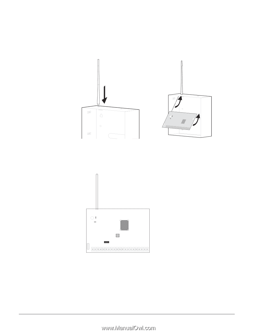
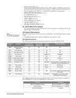
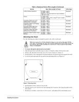
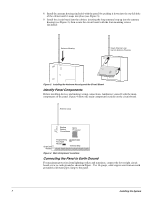
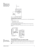
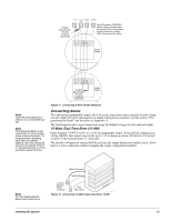
8. Install the antenna housing (included with the panel) by pushing it down into the top left hole of the cabinet until it snaps into place (see Figure 3). 9. Install the circuit board into the cabinet, inserting the loop antenna loop up into the antenna housing (see Figure 3), then secure the circuit board with the four mounting screws (included). Antenna Housing Insert Antenna Loop Up Into Antenna Housing Figure 3. Installing the Antenna Housing and the Circuit Board 60806G 32D D S F Identify Panel Components Before installing devices and making wiring connections, familiarize yourself with the main components of the panel. Figure 4 shows the main component locations on the circuit board. Antenna Loop Black Backup Micro Battery Processor Red Connections SnapCard Header Programming Touchpad Header EEPROM Terminal Strip Figure 4. Main Component Locations Connecting the Panel to Earth Ground For maximum protection from lightning strikes and transients, connect the lower-right circuit board screw to earth ground as shown in Figure . Use 16-gauge, solid copper wire from an earth grounded cold water pipe clamp to the panel. 7 Installing the System
-
 1
1 -
2
-
3
-
4
-
5
-
6
-
 7
7 -
 8
8 -
 9
9 -
 10
10 -
 11
11 -
 12
12 -
 13
13 -
 14
14 -
 15
15 -
 16
16 -
 17
17 -
18
-
19
-
20
-
21
-
22
-
23
-
24
-
25
-
26
-
27
-
28
-
29
-
30
-
31
-
32
-
33
-
34
-
35
-
36
-
37
-
38
-
39
-
40
-
41
-
42
-
43
-
44
-
45
-
46
-
47
-
48
-
49
-
50
-
51
-
52
-
53
-
54
-
55
-
56
-
57
-
58
-
59
-
60
-
61
-
62
-
63
-
64
-
65
-
66
-
67
-
68
-
69
-
70
-
71
-
72
-
73
-
74
-
75
-
76
 |
 |