GE 60-806-95R-16Z Installation Instructions - Page 14
Connecting Detection Devices to Panel Zone Inputs - concord
 |
UPC - 046188090938
View all GE 60-806-95R-16Z manuals
Add to My Manuals
Save this manual to your list of manuals |
Page 14 highlights
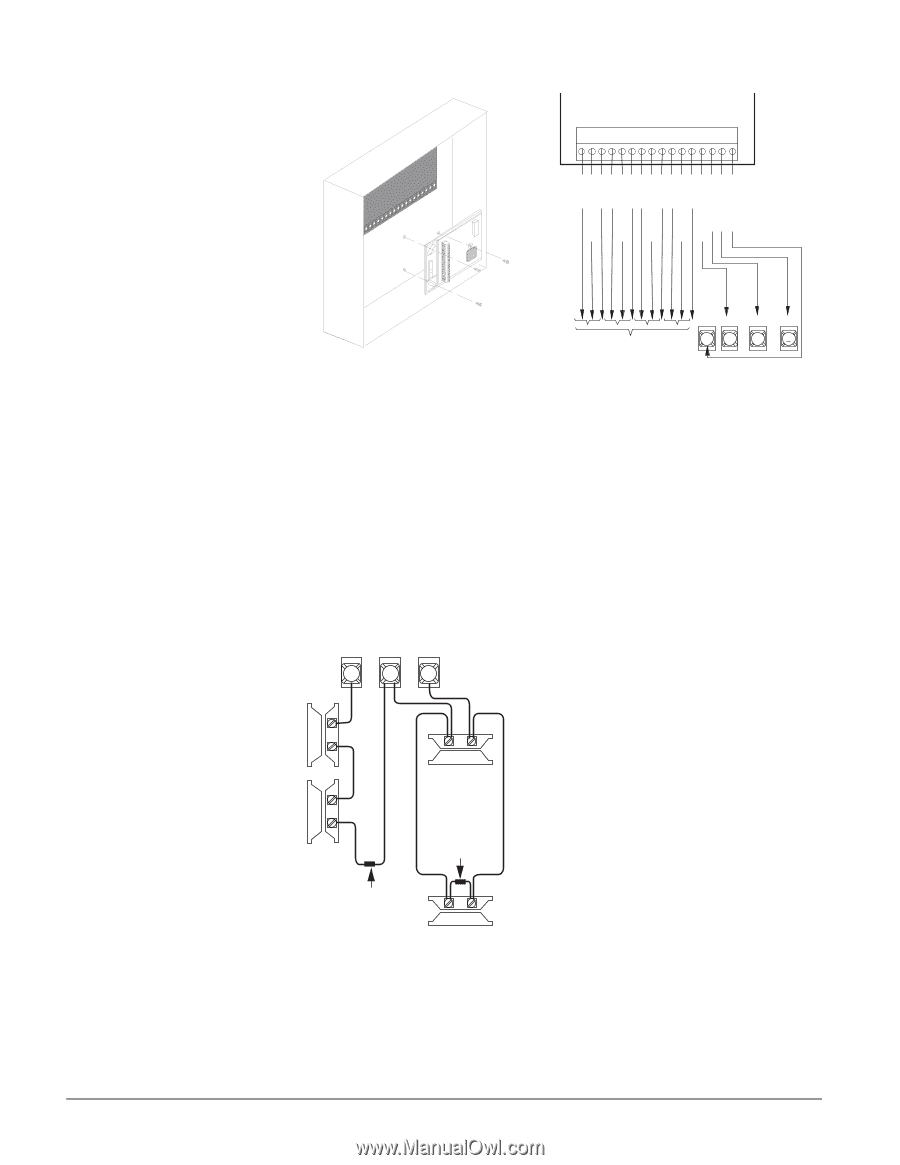
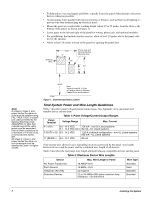
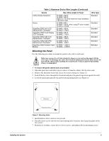
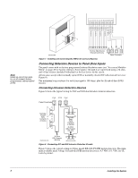
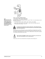
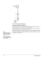
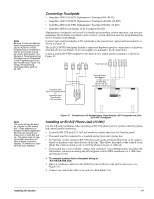
1 2 3 4 5 6 7 8 9 10 11 12 13 14 15 16 G N D (B L K ) B U S B (W H T ) B U S A (G R N ) + 1 2 V D C (R E D ) ZO N E 8 ZO N E C O M M O N ZO N E 7 ZO N E 6 ZO N E C O M M O N ZO N E 5 ZO N E 4 ZO N E C O M M O N ZO N E 3 ZO N E 2 ZO N E C O M M O N ZO N E 1 Note Install an end-of-line resistor on all unused, factory programmed, onboard panel zones. 8642137A.DSF To Zone Input Device (Shared Commons) Figure 7. Installing and Connecting the HIM in the Concord Express G N D +12V 3 4 A BUS B 5 6 Panel Terminals Connecting Detection Devices to Panel Zone Inputs The panel comes with six factory programmed onboard hardwire zones (see "Accessory Modules Menu" on page 40 for factory settings). Zone inputs 1 through 6 are supervised using a 2k-ohm, end-of-line resistor (included with panel) at the last device on the circuit. All six zones accept either normally open (N/O) or normally closed (N/C) detection devices (see Figure 8). The maximum loop resistance for each zone input is 300 ohms, plus the 2k end-of-line (EOL) resistor. Connecting Intrusion Detection Devices Figure 8 shows the typical wiring for N/C and N/O door/window intrusion detection. ZO N E 1 ZC O M ZO N E 2 Panel Terminals 9 10 11 Normally Closed (N/C) Contacts in Series Normally Open (N/O) Contacts in Parallel 2k Ohm EOL Resistor (49-454) 6 0 8 0 6 G 0 6 D .D S 4 2k Ohm EOL Resistor (49-454) Figure 8. Connecting N/C and N/O Intrusion Detection Circuits Figure 9 shows the typical wiring for Optex model RX-040 (PI) PIR motion detectors. The minimum available panel voltage for hardwired PIR motion detectors is 8.5 VDC (9.1 VDC for UL Listed systems). 9 Installing the System
-
 1
1 -
2
-
3
-
4
-
5
-
6
-
7
-
8
-
 9
9 -
 10
10 -
 11
11 -
 12
12 -
 13
13 -
 14
14 -
 15
15 -
 16
16 -
 17
17 -
 18
18 -
 19
19 -
20
-
21
-
22
-
23
-
24
-
25
-
26
-
27
-
28
-
29
-
30
-
31
-
32
-
33
-
34
-
35
-
36
-
37
-
38
-
39
-
40
-
41
-
42
-
43
-
44
-
45
-
46
-
47
-
48
-
49
-
50
-
51
-
52
-
53
-
54
-
55
-
56
-
57
-
58
-
59
-
60
-
61
-
62
-
63
-
64
-
65
-
66
-
67
-
68
-
69
-
70
-
71
-
72
-
73
-
74
-
75
-
76
 |
 |