GE 60-806-95R-16Z Installation Instructions - Page 17
Connecting Sirens - concord express alarm
 |
UPC - 046188090938
View all GE 60-806-95R-16Z manuals
Add to My Manuals
Save this manual to your list of manuals |
Page 17 highlights
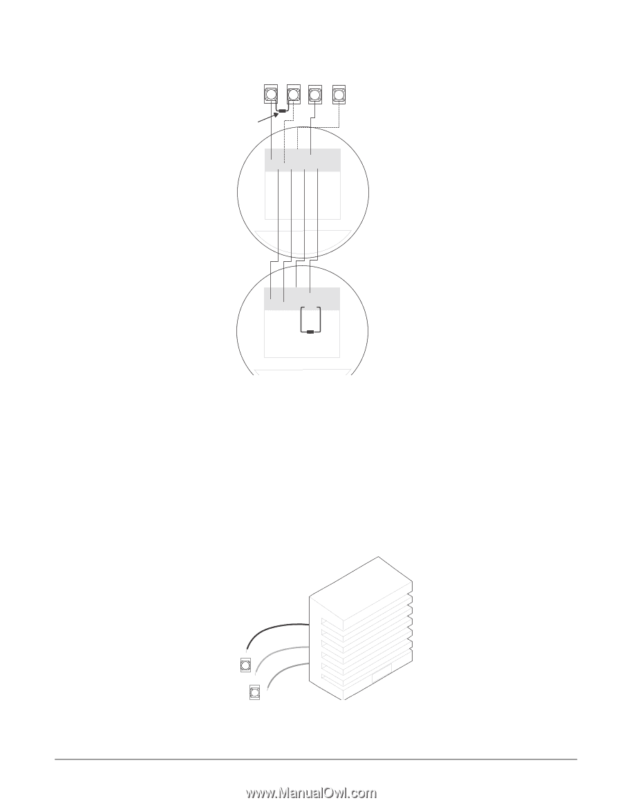
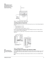
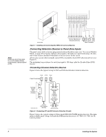
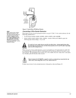
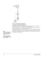
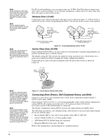
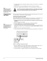
+12V 4 2k Ohm EOL Resistor (49-454) Locate at Last Device O U T2/ ZO N E OC 1 8 9 ZC O M 1 0 Panel Terminal 8 (OUT2/OC) Must be Set to Configuration Number 01500 for Connected Smoke Detectors to Reset After Canceling a Fire Alarm CC OONN +. +. .- .- M. M. O. O. Model 449AT CC OONN +. +. .- .- M. M. O. O. 2k Ohm EOL Resistor (49-454) Locate at Last Device Model 449AT Note Install all sirens/speakers indoors, in a concealed location. Note If the backup battery is not connected, or if the configuration of panel terminal 7 is programmed to anything other than the default (00410), then the combined currents of terminal 7 (OUT 1/+12) and terminal 4 (+12V) must not exceed 750 mA. Figure 11. Connecting 4-Wire Smoke Detectors Connecting Sirens Two onboard programmable outputs allow for siren connections when using the default setting of each output. For more information on output configuration numbers, see the section "Programming the Panel" and the tables in Appendix A. The following describes siren connections using the default settings of each onboard output. 15-Watt, Dual Tone Siren (13-469) Panel terminal 7 (OUT1/+12V) is a +12V programmable output. At the default configuration setting (00410), this output can provide up to 1.25 A during an alarm (650 mA for UL Listed systems) if the backup battery is connected. The default configuration setting (00410) activates the output during any audible alarm, allowing for a siren connection without changing the output configuration number. Note For UL Listed systems, Siren Verify must be on. Black (Common) Yellow (Steady) GND Concord Express Panel Terminals 3 O U T1/ +12V 7 Red (Not Used) 60806G 100D D S F Figure 12. Connecting 15-Watt, Dual-Tone Siren 13-469 Installing the System 12
-
 1
1 -
2
-
3
-
4
-
5
-
6
-
7
-
8
-
9
-
10
-
11
-
 12
12 -
 13
13 -
 14
14 -
 15
15 -
 16
16 -
 17
17 -
 18
18 -
 19
19 -
 20
20 -
 21
21 -
 22
22 -
23
-
24
-
25
-
26
-
27
-
28
-
29
-
30
-
31
-
32
-
33
-
34
-
35
-
36
-
37
-
38
-
39
-
40
-
41
-
42
-
43
-
44
-
45
-
46
-
47
-
48
-
49
-
50
-
51
-
52
-
53
-
54
-
55
-
56
-
57
-
58
-
59
-
60
-
61
-
62
-
63
-
64
-
65
-
66
-
67
-
68
-
69
-
70
-
71
-
72
-
73
-
74
-
75
-
76
 |
 |