GE 60-806-95R-16Z Installation Instructions - Page 9
Installing the, System
 |
UPC - 046188090938
View all GE 60-806-95R-16Z manuals
Add to My Manuals
Save this manual to your list of manuals |
Page 9 highlights
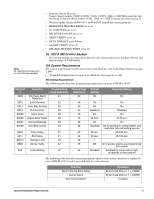
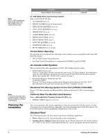
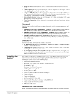
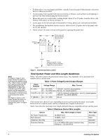
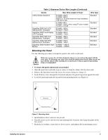
Installing the System Installing the System • Bus A and B: Input and output that provide communication between bus devices and the panel. • 2 Onboard Outputs: One 12-volt and one open-collector output that can be set up to activate other signalling devices, based on system events. • 6 Supervised Hardwire Zones: Factory programmed inputs for various hardwired detectors (see "Accessory Modules Menu" on page 40 for a list of factory programmed settings). Zone 6 can be set up in programming to accept 2-wire smoke detectors. • Built-In Radio Receiver: Allows use of GE Security 319.5 MHz. crystal and/or SAW Learn Mode wireless sensors and touchpads. • Phone Line Connection: Allows the panel to communicate with central monitoring stations and pagers. Touchpads The following describes the different touchpads that can be used for system programming and operation. • SuperBus 2000 2x16 LCD Alphanumeric Touchpad: Provides complete system program- ming and operation control. Displays system messages, and indicates system status. • SuperBus 2000 2x20 LCD/VFD Alphanumeric Touchpads: Provide complete system pro- gramming and operation control, display system messages and indicate system status. • SuperBus 2000 Fixed Display LCD Touchpad: Provides operation control and user pro- gramming access (not installer or dealer programming). Displays system messages and indicates system status. SnapCard™ The following SnapCards expand the system as described: • 8Z Input SnapCard: Provides eight additional hardwire zone inputs, of which two are dedi- cated for 2-wire smoke detectors. • 4 Output SnapCard: Provides four form C relay outputs that can be set up to activate other signalling devices, based on system events. • 4Z Input/2 Output Combo SnapCard: Provides three standard hardwire zone inputs, one 2-wire smoke detector loop input, and two outputs that can be set up to activate other signalling devices that are based on system events. This section describes how to install the system control panel. Before starting the installation, plan your system layout and programming using the worksheets provided in Appendix A. Installing the system consists of the following steps: • Determining the Panel Location • Identifying Total System Power and Wire Length Guidelines • Mounting the Panel • Identifying Panel Main Components • Installing Optional SnapCards • Installing Optional HIMs • Connecting Detection Devices to Panel Zone Inputs • Connecting Sirens • Connecting Touchpads • Installing an RJ-31X Phone Jack • Connecting the Phone Line to the Panel with a DB-8 Cord • Connecting the AC Power Transformer • Powering Up the Panel Determine the Panel Location Before permanently mounting the panel, determine the location using the following guidelines: 4
-
 1
1 -
2
-
3
-
 4
4 -
 5
5 -
 6
6 -
 7
7 -
 8
8 -
 9
9 -
 10
10 -
 11
11 -
 12
12 -
 13
13 -
 14
14 -
15
-
16
-
17
-
18
-
19
-
20
-
21
-
22
-
23
-
24
-
25
-
26
-
27
-
28
-
29
-
30
-
31
-
32
-
33
-
34
-
35
-
36
-
37
-
38
-
39
-
40
-
41
-
42
-
43
-
44
-
45
-
46
-
47
-
48
-
49
-
50
-
51
-
52
-
53
-
54
-
55
-
56
-
57
-
58
-
59
-
60
-
61
-
62
-
63
-
64
-
65
-
66
-
67
-
68
-
69
-
70
-
71
-
72
-
73
-
74
-
75
-
76
 |
 |