GE 60-806-95R-16Z Installation Instructions - Page 46
Onboard Options Menu, Device ID, Status Beeps, Key Beeps, Output 1, 2, 3, 4 081000-output 1 081010-
 |
UPC - 046188090938
View all GE 60-806-95R-16Z manuals
Add to My Manuals
Save this manual to your list of manuals |
Page 46 highlights
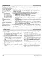
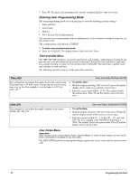
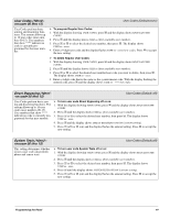
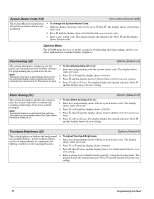
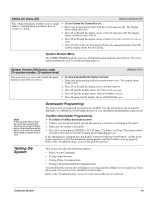
Device ID This menu lets you change a bus device ID number when replacing a defective bus device. Acc. Modules-Bus Devices (Default=none) ¾ To change a Device ID: 1. With the display showing the desired device, press ƒ twice. The display shows DEVICE ID (current ID). 2. Enter the ID of the new bus device. The display flashes the entered selection. Press ƒ and the display shows the new setting. 3. Exit programming mode. 4. Remove AC and battery power from the panel. 5. Replace the defective bus device with the new one. 6. Apply AC and battery power to the panel. Status Beeps Acc. Modules-Bus Devices (Default=on) This setting determines whether or not the selected touchpad sounds status beeps. Each touchpad can be set individually. This feature is usually turned off if a touchpad is located in or near bedrooms to avoid disturbing persons sleeping. Note For UL Listed systems, Status Beeps must be turned on. ¾ To turn touchpad Status Beeps on or off: 1. With the display showing the desired touchpad, press ƒ then B once. The display shows TOUCHPAD OPTIONS. 2. Press ƒ and the display shows STATUS BEEPS OFF/ON (current setting). 3. Press 1 (off) or 2 (on) to select the desired setting. The display flashes the entered selection. Press ƒ and the display shows the new setting. Key Beeps This setting determines whether or not selected touchpads sound beeps when their buttons are pressed. This feature is usually turned off if a touchpad is located in or near bedrooms to avoid disturbing persons sleeping. Acc. Modules-Bus Devices (Default=on) ¾ To turn Key Beeps on or off: 1. With the display showing the desired touchpad, press ƒ + B + ƒ + B. The display shows KEY BEEPS OFF/ON (current setting). 2. Press 1 (off) or 2 (on) to select the desired setting. The display flashes the entered selection. Press ƒ and the display shows the new setting. The following describes how to program the settings that appear under SNAPCARDS. Output 1, 2, 3, 4 (081000-output 1) (081010-output 2) (081020-output 3) (081030-output 4) Acc. Modules-SnapCards (Defaults: Output 1=01400, Output 2=00410, Output 3=00903, Output 4=01003) This setting lets you assign the 5-digit configuration number for each SnapCard relay output that determines which system event activates the output and the duration or time the output is activated. The first three digits represent the trigger number of an event such as an alarm, open sensor, or arming the system. The last two digits represent how the output responds such as momentary, sustained (or latched), or for a preset time. Tables A6-A10 in "Appendix A" identify system event trigger and response numbers. ¾ To assign configuration numbers to SnapCard Relay outputs: 1. With the display showing SNAPCARDS, press ƒ. The display shows OUTPUT PROGRAMMING. 2. Press ƒ again and the display shows OUTPUT 1. 3. Press A or B to select the desired output (1-4), then press ƒ. The display shows OUTPUT n (current setting). 4. Enter the desired 5-digit configuration number for this output. The display flashes the entered number. Press ƒ and the display shows the new setting. Onboard Options Menu The ONBOARD OPTIONS menu lets you set up the following built-in options: INPUTS-this menu lets you set panel zone input 6 for 2-wire smoke operation and turn the smoke verification feature off/on. 41 Programming the Panel
-
 1
1 -
2
-
3
-
4
-
5
-
6
-
7
-
8
-
9
-
10
-
11
-
12
-
13
-
14
-
15
-
16
-
17
-
18
-
19
-
20
-
21
-
22
-
23
-
24
-
25
-
26
-
27
-
28
-
29
-
30
-
31
-
32
-
33
-
34
-
35
-
36
-
37
-
38
-
39
-
40
-
 41
41 -
 42
42 -
 43
43 -
 44
44 -
 45
45 -
 46
46 -
 47
47 -
 48
48 -
 49
49 -
 50
50 -
 51
51 -
52
-
53
-
54
-
55
-
56
-
57
-
58
-
59
-
60
-
61
-
62
-
63
-
64
-
65
-
66
-
67
-
68
-
69
-
70
-
71
-
72
-
73
-
74
-
75
-
76
 |
 |