GE 60-806-95R-16Z Installation Instructions - Page 19
Connecting Touchpads, Installing an RJ-31X Phone Jack 13-081
 |
UPC - 046188090938
View all GE 60-806-95R-16Z manuals
Add to My Manuals
Save this manual to your list of manuals |
Page 19 highlights
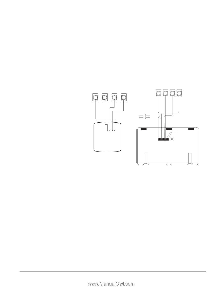
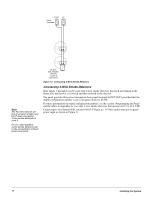
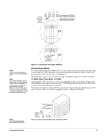
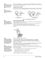
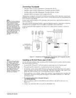
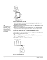
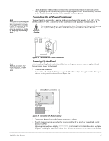
Note Be sure to have an alphanumeric (programming) touchpad on hand for on-site programming in installations that do not include one as part of the final system configuration. This programming touchpad can be connected to the Programming Touchpad Header (see Figure 15) using a Programming Touchpad Cable (part no. 60-791). Connecting Touchpads • SuperBus 2000 2x16 LCD Alphanumeric Touchpad (60-746-01) • SuperBus 2000 2x20 LCD Alphanumeric Touchpads (60-803, 60-809) • SuperBus 2000 2x20 VFD Alphanumeric Touchpad (60-804, 60-810) • SuperBus 2000 Fixed Display LCD Touchpad (60-820) Alphanumeric touchpads can be used for installer programming, system operation, and user programming. Fixed display touchpads can be used for system operation and user programming but not for installer programming. Connect 2x16 and fixed display LCD touchpads to the panel power output and bus terminals as shown in Figure 15. The 2x20 LCD/VFD touchpads include a supervised hardwire input for connection to a hardwire detection device (see Figure 15 for an example of a normally closed connection). Connect 2x20 LCD/VFD touchpads to the panel power output and bus terminals as shown in Figure 15. GND +12V 3 4 A BUS B 5 6 G N D +12V B U S A B U S B Panel Terminals 3 4 5 6 SuperBus 2000 2x16 LCD Alphanumeric or SuperBus 2000 Fixed English LCD Touchpad Optional Switch with Magnet 2k Ohm EOL Resistor 49-454 (Locate at Last Device) +12V/Red BUS A/Green Bus B/White GND/Black Note The panel cannot be used on a digital or PBX phone line. These systems are designed only for digital type devices that operate anywhere from 5 volts DC and up. The panel uses an analog modem and does not have a digital converter, adapter, or interface to operate with such systems. Figure 15. Connecting 2x16 Alphanumeric, Fixed Display LCD Touchpads and 2x20 LCD/VFD Touchpads Installing an RJ-31X Phone Jack (13-081) Use the following guidelines when installing an RJ-31X phone jack for system control by phone and central station monitoring. • Locate the RJ-31X jack (CA-38A in Canada) no further than five feet from the panel. • The panel must be connected to a standard analog (loop-start) phone line. • For full line seizure, install an RJ-31X phone jack on the premises phone line so the panel is ahead of all phones and other devices on the line. This allows the panel to take control of the phone line when an alarm occurs even if the phone is in use or off-hook. • If an analog line is not available, contact your customers' telecommunications specialist and tell him/her you need an analog line off the phone switch (PBX mainframe) or a 1FB (standard business line). ¾ To connect a phone line to the panel using an RJ-31X/CA-38A jack: 1. Run a 4-conductor cable from the TELCO protector block to the jack location (see A in Figure 16). 2. Connect one end of the cable to the jack (see B in Figure 16). Installing the System 14
-
 1
1 -
2
-
3
-
4
-
5
-
6
-
7
-
8
-
9
-
10
-
11
-
12
-
13
-
 14
14 -
 15
15 -
 16
16 -
 17
17 -
 18
18 -
 19
19 -
 20
20 -
 21
21 -
 22
22 -
 23
23 -
 24
24 -
25
-
26
-
27
-
28
-
29
-
30
-
31
-
32
-
33
-
34
-
35
-
36
-
37
-
38
-
39
-
40
-
41
-
42
-
43
-
44
-
45
-
46
-
47
-
48
-
49
-
50
-
51
-
52
-
53
-
54
-
55
-
56
-
57
-
58
-
59
-
60
-
61
-
62
-
63
-
64
-
65
-
66
-
67
-
68
-
69
-
70
-
71
-
72
-
73
-
74
-
75
-
76
 |
 |