GE 60-806-95R-16Z Installation Instructions - Page 18
Connecting Siren Drivers, Self-Contained Sirens, and Bells
 |
UPC - 046188090938
View all GE 60-806-95R-16Z manuals
Add to My Manuals
Save this manual to your list of manuals |
Page 18 highlights
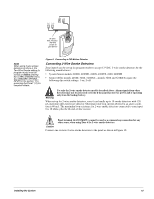
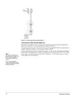
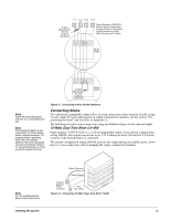
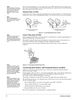
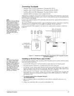
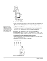
Note Some versions of this siren may have two wires of each color. Only one black wire and one yellow wire are needed for panel connections. Note For UL Listed systems, Siren Verify must be on and the 2k end-of-line resistor installed. For UL Listed installations, you can connect only one 15-Watt, Dual-Tone Siren to panel terminals 3 and 7 as shown in Figure 12. For all other installations, connect up to two sirens. This siren does not require an end-of-line resistor. Hardwire Siren (13-046) Connect one or two sirens to the panel with supervision as shown in Figure 13. If Siren Verify is turned off (see the section "Programming the Panel"), the 2k end-of-line resistor is not required. G N D O U T1/ +12V 3 Panel 7 Terminals Black Red G N D O U T1/ +12V 3 7 Panel Terminals Black Red Note Piezo siren connections to terminal 8 require a 2k end-of-line resistor that can be located at the panel since it does not supervise the circuit. 2k Ohm EOL Resistor 49-454 (Locate at Siren) 2k Ohm EOL Resistor 49-454 (Locate at Last Siren) Figure 13. Connecting Hardwire Siren 13-046 Interior Piezo Siren (30-006) Panel terminal 8 (OUT2/OC) is an open-collector (switched path-to-ground), programmable output that can handle up to a 200 mA current. The default setting (01710) activates the output for status and alarm tones, which allows for a piezo siren connection without changing the output configuration number. Connect the piezo siren to the panel terminals with a 2k end-of-line resistor as shown in Figure 14. +12V Panel Terminals 4 O U T2/ OC 8 Black 2k Ohm Resistor 49-454 Red Note If using an external power supply instead of panel terminal 4, the supply voltage must be limited to 9.5 VDC maximum and the negative side of the power supply must be connected to panel ground (terminal 3). Note If the backup battery is not connected, or if the configuration of panel terminal 7 is programmed to anything other than the default (00410), then the combined currents of terminal 7 (OUT 1/+12) and terminal 4 (+12V) must not exceed 750 mA. Figure 14. Connecting an Interior Piezo Siren Connecting Siren Drivers, Self-Contained Sirens, and Bells Power for a siren driver, self-contained siren, or bell can be connected to panel terminals 7 (OUT1/+12V) and 3 (GND). Panel terminal 7 (OUT1/+12V) is a +12-volt programmable output. At the default configuration setting (00410), this output can provide up to 1.25 A during an alarm (650 mA for UL Listed systems) if the backup battery is connected. The default configuration setting (00410) activates the output during any audible alarm. The following siren drivers, self-contained sirens, and bells have been tested and found compatible for use with the panel: • Moose Models MPI-11 (use only 8-ohm speaker loads), MP-47, MP-47B • Altronix Model ALSD2 (4- or 8-ohm speaker loads) • ATW Models DT-24, DS508 (both self-contained) • Wheelock MB-G6-12 Six-inch, 12V Bell Refer to the manufacturer's documentation for installation details. 13 Installing the System
-
 1
1 -
2
-
3
-
4
-
5
-
6
-
7
-
8
-
9
-
10
-
11
-
12
-
 13
13 -
 14
14 -
 15
15 -
 16
16 -
 17
17 -
 18
18 -
 19
19 -
 20
20 -
 21
21 -
 22
22 -
 23
23 -
24
-
25
-
26
-
27
-
28
-
29
-
30
-
31
-
32
-
33
-
34
-
35
-
36
-
37
-
38
-
39
-
40
-
41
-
42
-
43
-
44
-
45
-
46
-
47
-
48
-
49
-
50
-
51
-
52
-
53
-
54
-
55
-
56
-
57
-
58
-
59
-
60
-
61
-
62
-
63
-
64
-
65
-
66
-
67
-
68
-
69
-
70
-
71
-
72
-
73
-
74
-
75
-
76
 |
 |
