GE 60-806-95R-16Z Installation Instructions - Page 24
Programming Tier 1 Menu Items, Programming Tier 2 Menu Items
 |
UPC - 046188090938
View all GE 60-806-95R-16Z manuals
Add to My Manuals
Save this manual to your list of manuals |
Page 24 highlights
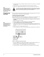
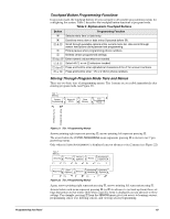
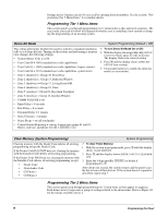
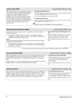
Settings in tier 2 menus can also be accessed by entering shortcut numbers. See the section, "Programming Tier 2 Menu Items" for complete details. Programming Tier 1 Menu Items This section guides you through programming tier 1 menu items as they appear in sequence. The exact order you need to follow will depend on whether you're installing a new system or changing the programming of an existing system. Demo Kit Mode System Programming (Default = Off) This setting determines whether the panel is used for a standard installation (off) or as a demo kit (on). Turning on this feature and performing a memory clear changes the following settings: • System Master Code = 1234 • User Code 00 = 1001 (standard user code capabilities) • User Code 01 = 1002 (standard user code capabilities, bypass sensors) • User Code 04 = 1122 (standard user code capabilities, system tests) • Zone 1 (hardwire) = Group 10, Front Door • Zone 2 (hardwire) = Group 13, Bedroom Window ¾ To turn Demo Kit Mode On or Off: 1. With the display showing DEMO KIT OFF/ON (current setting), press 1 (off) or 2 (on). The display flashes the entered setting. 2. Press ƒ and the display shows DEMO KIT OFF/ON (new setting). 3. Clear panel memory to enable the demo kit mode (see next menu). • Zone 3 (hardwire) = Group 17, Living Room PIR • Zone 4 (hardwire) = Group 01, Panic • Zone 5 (wireless) = Group 01, Keychain Touchpad • Zone 6 (wireless) = Group 13, Kitchen Window • COMM FAILURE = off • Entry Delay = 8 seconds • Exit Delay = 8 seconds • Extended Delay = 1 minute • Siren Timeout = 2 minutes • Status Beeps = on (all touchpads) • Central Station Reporting = sensors learned into groups 01 and 03, Duress code use, and phone test (8 + CODE + 2) Clear Memory (System Programming) System Programming Clearing memory with the Dealer Code deletes all existing programming except the Dealer Code. If the Dealer Code HAS NOT been set, clearing the memory with the Installer Code deletes all existing programming. If the Dealer Code HAS been set, clearing the memory with the Installer Code deletes all existing programming except: • Dealer Code • Downloader Code • CS Phone 1 • CS Phone 2 ¾ To clear Panel Memory: 1. With the system in program mode, press B until the display shows CLEAR MEMORY. 2. Press ƒ and the display shows ENTER CODE TO CLEAR MEMORY. 3. Enter the 4-digit installer CODE (or dealer if programmed) + ƒ. After about one second, the system restarts and the panel scans the bus to learn all bus devices. If the system doesn't respond as described, repeat step 3. Programming Tier 2 Menu Items This section guides you through programming tier 2 menu items as they appear in sequence. Each menu on tier 2 represents a group of settings related to the menu name. Refer to Figure 22 for the menus available on tier 2. 19 Programming the Panel
-
 1
1 -
2
-
3
-
4
-
5
-
6
-
7
-
8
-
9
-
10
-
11
-
12
-
13
-
14
-
15
-
16
-
17
-
18
-
 19
19 -
 20
20 -
 21
21 -
 22
22 -
 23
23 -
 24
24 -
 25
25 -
 26
26 -
 27
27 -
 28
28 -
 29
29 -
30
-
31
-
32
-
33
-
34
-
35
-
36
-
37
-
38
-
39
-
40
-
41
-
42
-
43
-
44
-
45
-
46
-
47
-
48
-
49
-
50
-
51
-
52
-
53
-
54
-
55
-
56
-
57
-
58
-
59
-
60
-
61
-
62
-
63
-
64
-
65
-
66
-
67
-
68
-
69
-
70
-
71
-
72
-
73
-
74
-
75
-
76
 |
 |
